Efficient and energy-saving concrete water reducing agent blending device

A concrete water reducer, high-efficiency and energy-saving technology, applied in the field of blending equipment, can solve the problems of increasing operating costs of enterprises, speeding up the uniform mixing of water reducing agents, and insufficient production efficiency, so as to reduce electricity costs and improve mixing uniformity , cost-saving effect

Pending Publication Date: 2021-08-06
山东华伟银凯建材科技股份有限公司
View PDF1 Cites 2 Cited by
  • Summary
  • Abstract
  • Description
  • Claims
  • Application Information

AI Technical Summary

Problems solved by technology

[0004] After a large number of searches, it was found that the prior art, the publication number is CN213198202U, discloses a high-strength energy-saving concrete water reducer mixing device, including a shell, the top of the left side of the shell is bolted with a receiving hopper, the receiving hopper The center of the bottom is connected with a feed pipe, the bottom end of the feed pipe communicates with the inner cavity of the housing, the top of the housing is bolted with a fixed frame, and the center of the top of the fixed frame is bolted with a protective Cover; the utility model can speed up the uniform mixing speed of the water reducing agent through the arrangement of the shell, the fixed frame, the motor, the driving gear, the stirring shaft, the driven gear and the stirring blade, so that the water reducing agent and the concrete are evenly mixed , which can improve the mixing efficiency of concrete, and solve the problem that the existing water reducer mixing device will cause eddy currents in the material during the mixing process, which will affect the mixing effect of concrete and water reducer, and the materials cannot be mixed evenly, thus The problem of reducing the efficiency of concrete mixing
[0005] To sum up, in the actual use of the existing concrete water reducing agent mixing equipment, the raw materials of the concrete water reducing agent will have a certain degree of agglomeration before being put into the mixing equipment, and the agglomerated raw materials will be agglomerated after being put into the mixing equipment The blending equipment cannot be crushed, which leads to some agglomerated raw materials after blending, which reduces the effect of blending and affects the subsequent processing. In order to solve the above problems, the raw materials need to be ground, so that It is necessary to add additional grinding equipment to crush the agglomerated raw materials, but it will increase the operating cost of the enterprise, the actual production is not efficient enough, and the existing stirring blending equipment will accumulate materials near the drive shaft during operation , that is, the fluidity of the material around the drive shaft is lower than that of the material far away from the drive shaft, which greatly reduces the mixing uniformity of the material

Method used


Image

  • Efficient and energy-saving concrete water reducing agent blending device
  • Efficient and energy-saving concrete water reducing agent blending device
  • Efficient and energy-saving concrete water reducing agent blending device

Examples


Embodiment 1

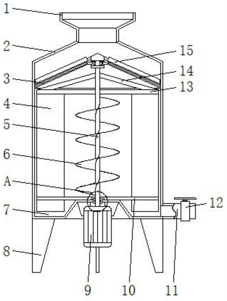
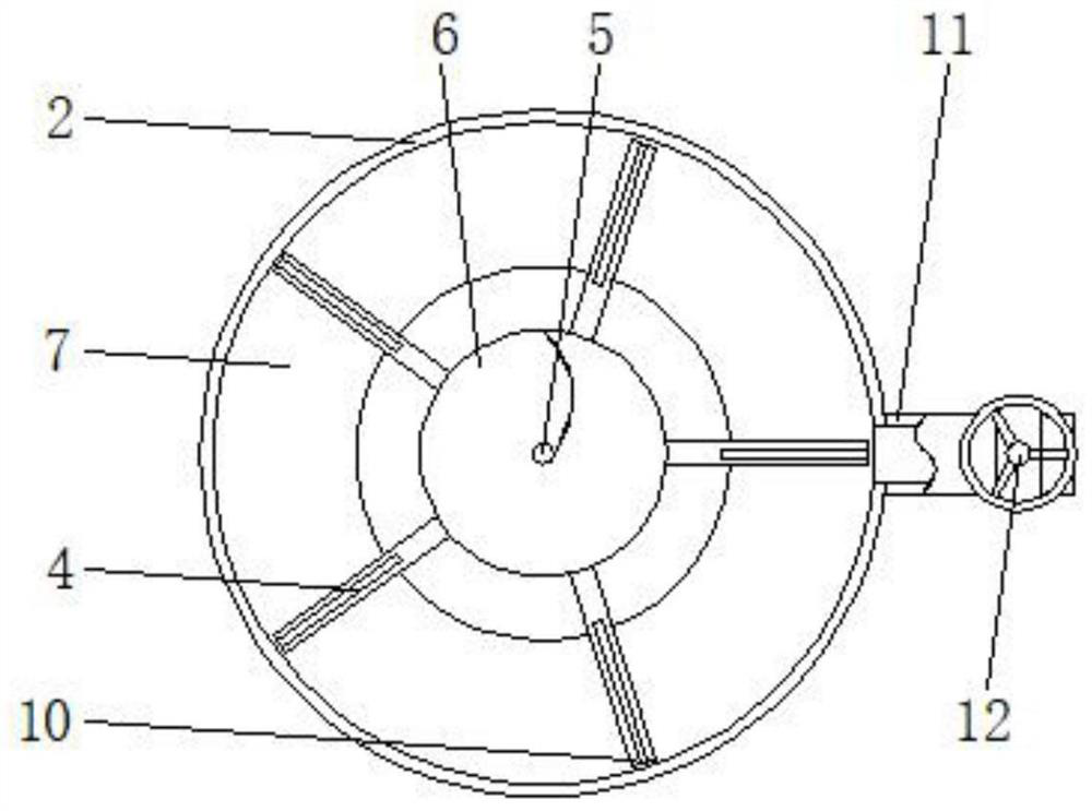
[0032] A high-efficiency and energy-saving concrete water-reducing agent mixing device, including a tank body 2, a grinding plate 3, a transmission shaft 5, a strand 6, a sedimentation tank 7, a first shaft sleeve 20 and a second shaft sleeve 23, and the upper surface of the tank body 2 A feed hopper 1 is provided, support legs 8 distributed in a circular array are welded on the lower surface of the tank body 2, a grinding plate 3 is arranged inside the upper end of the tank body 2, a sedimentation tank 7 is arranged inside the lower end of the tank body 2, and the bottom of the tank body 2 One side of the surface is provided with a discharge pipe 11, and the surface of the discharge pipe 11 is provided with a valve 12, and the discharge pipe 11 is connected with the interior of the sedimentation tank 7; the blended water reducer raw materials can be deposited in the sedimentation tank 7, and the staff The valve 12 can be opened, and the motor 9 drives the rotation of the mixin...

Embodiment 2

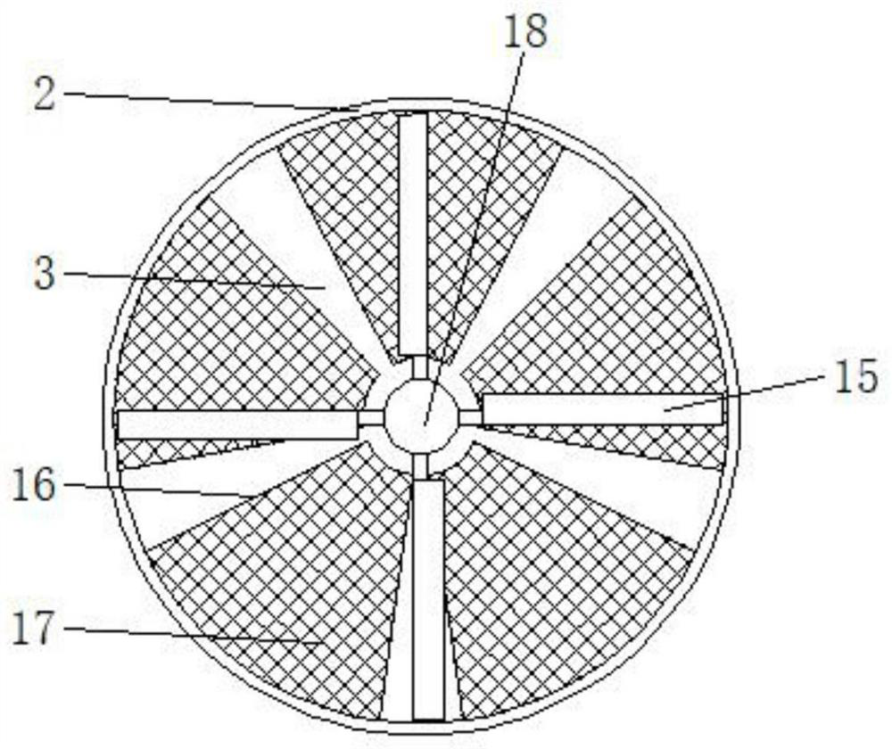
[0034] The lower surface of the tank body 2 is provided with a motor 9. As is well known to those skilled in the art, the provision of the motor 9 is commonplace, which all belong to conventional means or common knowledge, and will not be repeated here. Those skilled in the art can according to their needs or To facilitate optional matching, the upper surface of the motor 9 is provided with a drive shaft 5 that runs through the lower end of the tank body 2, and the upper end of the drive shaft 5 runs through the center of the grinding plate 3 and is connected to a first limit block 18, the outer wall of the first limit block 18 Stirring rods 15 distributed in a circular array are welded, and the surface of the transmission shaft 5 is provided with twisted pieces 6. When the transmission shaft 5 rotates, the materials around the transmission shaft 5 are transported upwards through the twisted pieces 6 and accumulated on the surface of the material layer. Therefore, the material ...

Embodiment 3

[0038] The surface of the grinding plate 3 is embedded with screens 17 distributed in a circular array, the circular position of the grinding plate 3 is embedded with a first bushing 20, the first bushing 20 is embedded with a first bearing 21, and the drive shaft 5 The upper end is rotatably inserted inside the first bushing 20 , and the outer wall of the upper end of the transmission shaft 5 is provided with a second limiting block 19 , and the first limiting block 18 and the second limiting block 19 are symmetrically distributed on both sides of the first bushing 20 . The first bearing 21 can ensure the smooth rotation of the transmission shaft 5 inside the first sleeve 20, reduce the mechanical wear of the transmission shaft 5, and the upper surface of the first limit block 18 adopts a tapered design, which can reduce the problem of material retention. And the first limit block 18 and the second limit block 19 block the gap between the transmission shaft 5 and the first sha...


PUM


Abstract

The invention discloses an efficient and energy-saving concrete water reducing agent blending device which comprises a tank body, a grinding plate, a transmission shaft, a twisting piece, a deposition tank, a first shaft sleeve and a second shaft sleeve; the grinding plate is arranged in the upper end of the tank body, the deposition tank is arranged in the lower end of the tank body, and a motor is arranged on the lower surface of the tank body; the transmission shaft penetrating through the lower end of the tank body is arranged on the upper surface of the motor, the upper end of the transmission shaft penetrates through the grinding plate and is connected with a first limiting block, a stirring rod is welded to the outer wall of the first limiting block, the twisting piece is arranged on the surface of the transmission shaft, and first connecting rods and second connecting rods are arranged at the two ends of the transmission shaft; and mixing plates are embedded between the first connecting rods and the second connecting rods, and screens distributed in a circular array are embedded in the surface of the grinding plate. The stirring rod, the twisting piece and the material mixing plate are synchronously driven to rotate through the transmission shaft, so that fed raw materials can be synchronously ground, the blending uniformity can be improved, and the actual use effect is better.

Description

technical field [0001] The invention relates to the technical field of mixing equipment, in particular to a high-efficiency and energy-saving concrete water reducing agent mixing device. Background technique [0002] Water reducer is a concrete admixture that can reduce the amount of mixing water while maintaining the slump of concrete basically unchanged. Most of them are anionic surfactants, such as lignosulfonate, naphthalenesulfonate formaldehyde polymer, etc. After being added to the concrete mixture, it can disperse the cement particles, improve its workability, reduce the unit water consumption, improve the fluidity of the concrete mixture; or reduce the unit cement consumption and save cement. [0003] In the production process of concrete superplasticizer, since various raw materials need to be mixed, blending equipment is needed to uniformly mix the raw materials for subsequent processing. [0004] After a large number of searches, it was found that the prior art...

Claims


Application Information

Patent Timeline
Patent Type & Authority Applications(China)
IPC IPC(8): B01F7/18B01F7/24B01F13/10B01F15/02B01F3/20B01F23/70
CPCB01F23/71B01F23/713B01F27/091B01F27/92B01F27/90B01F33/83B01F35/71805
Inventor 张明任绪波赵锴贾蕊丽贾吉堂
Owner 山东华伟银凯建材科技股份有限公司
Why Eureka
Try Eureka