Steel-concrete composite beam and concrete filled steel tubular column joint and construction method

A technology for concrete-filled steel tubular columns and reinforced concrete slabs, which is applied in the direction of construction and building structure, can solve the problems of affecting the use function, tearing and damage of concrete-filled steel tubular columns, residual stress, etc. The effect of improving the bearing capacity

Pending Publication Date: 2021-08-06
HARBIN INST OF TECH
View PDF15 Cites 0 Cited by
  • Summary
  • Abstract
  • Description
  • Claims
  • Application Information

AI Technical Summary

Problems solved by technology

[0004] The present invention aims to solve the problem that when the U-shaped steel-concrete composite beam is connected with the T-shaped or L-shaped steel pipe concrete column in the existing frame joints, the outer upper flange will seriously affect the use function; while the U-shaped steel-concrete composite beam and the T-shaped Or when the L-shaped steel tube concrete column is connected, the end of the longitudinally stressed steel bar in the reinforced concrete floor slab is directly welded to the steel tube concrete column. There is a large residual stress in the steel tube, and the plasticity is reduced. When the force is large, the steel bar transmits force to the weld. , the steel-concrete composite beam and steel-concrete column joints and construction method are provided by the tearing failure of the steel-filled steel pipe column at the weld, which brings about a huge potential safety hazard.

Method used


Image

  • Steel-concrete composite beam and concrete filled steel tubular column joint and construction method
  • Steel-concrete composite beam and concrete filled steel tubular column joint and construction method
  • Steel-concrete composite beam and concrete filled steel tubular column joint and construction method

Examples


specific Embodiment approach 1

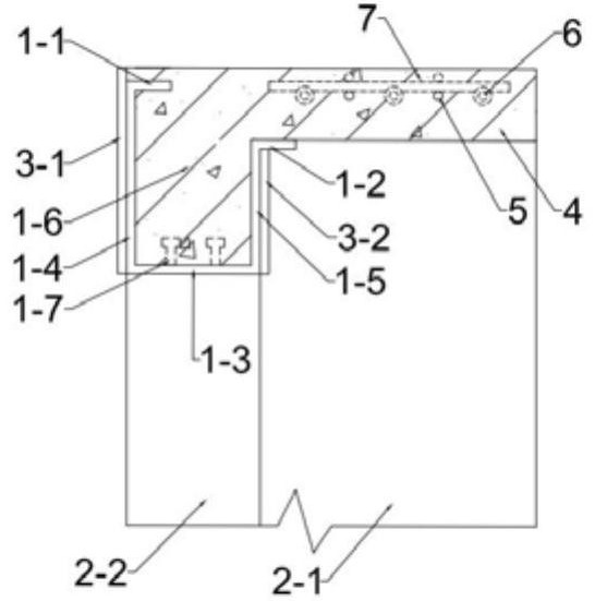
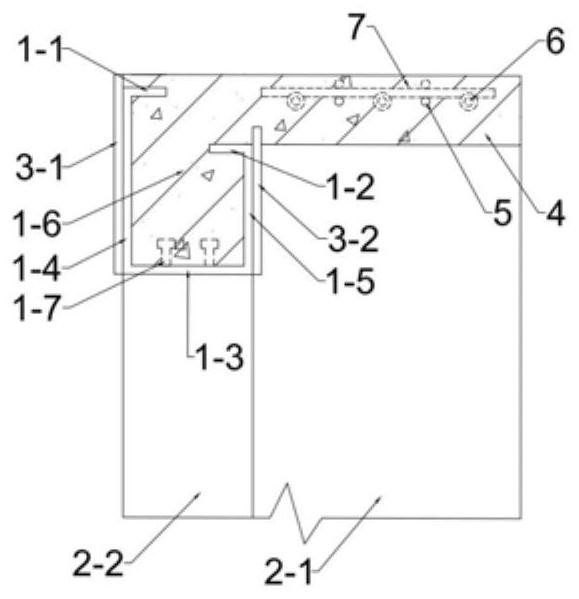
[0025] Specific implementation mode one: combine Figure 1-Figure 4 Describe this embodiment mode, a kind of steel-concrete composite beam and steel tube concrete column joint described in this embodiment mode, it comprises steel-concrete composite beam 1, steel tube concrete column 2, reinforced concrete plate 4 and two connecting end plates 3, steel tube The concrete column 2 is vertically arranged, the steel-concrete composite beam 1 and the reinforced concrete slab 4 are integrally arranged, and one end of the steel-concrete composite beam 1 and one end of the reinforced concrete slab 4 are both fixedly connected to the outer wall of the steel tube concrete column 2, two The connecting end plate 3 is installed on the steel-concrete composite beam 1 and the steel tube concrete column 2 .

[0026] In this embodiment, the cross section of the steel tube of the concrete filled steel tube column 2 is one of L-shape or T-shape.

specific Embodiment approach 2

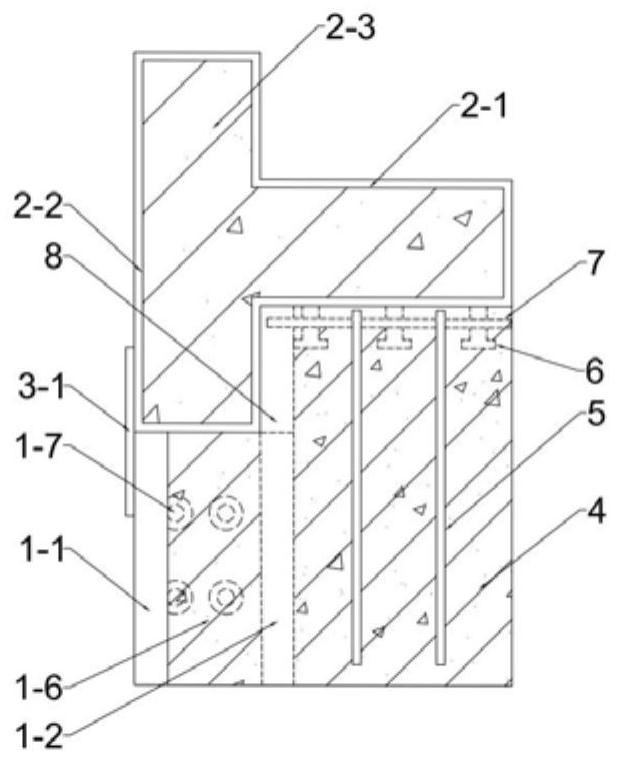
[0027] Specific implementation mode two: combination Figure 1-Figure 4 Describe this embodiment mode, a steel-concrete composite beam and concrete-filled steel tube column joint described in this embodiment mode, the steel tube concrete column 2 includes a vertical column limb 2-1, a parallel column limb 2-2 and a concrete 2-3 inside the column, vertical The column limb 2-1 is fixedly connected with the parallel column limb 2-2 to form a steel pipe body, and the concrete 2-3 inside the column is arranged in the steel pipe body. Other methods are the same as in the first embodiment.

specific Embodiment approach 3

[0028] Specific implementation mode three: combination Figure 1-Figure 4 Describe this embodiment, a steel-concrete composite beam and a steel pipe concrete column joint described in this embodiment, the steel-concrete composite beam 1 includes a lower flange 1-3, an outer web 1-4, and an inner web 1-5 1. Concrete 1-6 inside the beam and multiple shear connectors 1-7; the outer web 1-4 and inner web 1-5 are installed in parallel on the lower flange 1-3, and the inner concrete 1-6 of the beam is installed on the outer side The web 1-4, the inner web 1-5 and the lower flange 1-3, the outer web 1-4, the inner web 1-5 and the lower flange 1-3 are fixedly connected with the steel tube concrete column 2, and more A shear connector 1-7 is welded and installed on the upper end face of the lower flange 1-3. The shear connectors 1-7 are one of studs, bolts or angle steel. Other methods are the same as in the first embodiment.


PUM


Abstract

The invention discloses a steel-concrete composite beam and concrete filled steel tubular column joint and a construction method, relates to a composite joint and a joint construction method, and aims to solve the problems that when a U-shaped steel-concrete composite beam is connected with a T-shaped or L-shaped concrete filled steel tubular column in an existing frame joint, an outer side upper flange is turned outwards, and the use function is seriously influenced; and meanwhile, when the U-shaped steel-concrete composite beam is connected with the T-shaped or L-shaped concrete filled steel tubular column, the end of a longitudinal stressed steel bar in a reinforced concrete floor is directly welded to the concrete filled steel tubular column, a steel tube has relatively large residual stress, the plasticity is reduced, when the stress is relatively large, the steel bar transmits force to a welding seam, the concrete filled steel tubular column is torn and damaged at the welding position, and the huge potential safety hazard is brought. The concrete filled steel tubular column is vertically arranged, one end of the steel-concrete composite beam and one end of a reinforced concrete plate are both fixed to the outer side wall of the concrete filled steel tubular column, and two connecting end plates are installed on the steel-concrete composite beam and the concrete filled steel tubular column. The invention belongs to the field of building structures.

Description

technical field [0001] The invention relates to a combined node and a node construction method, in particular to a steel-concrete composite beam and steel tube concrete column node and a construction method. Background technique [0002] U-shaped steel-concrete composite beam has the advantages of high bearing capacity, high rigidity, good seismic performance, small cross-sectional size, fast construction speed, good fire resistance, smooth wall surface after construction, and good construction effect. It is often used with concrete filled steel pipe columns. Compatible with reinforced concrete floors. However, when the U-shaped composite beam is connected with the T-shaped or L-shaped concrete-filled steel pipe column, the outer upper flange eversion will seriously affect the use function, and will affect the external wall insulation and decoration construction. [0003] The negative bending moment at the frame joint is relatively large. When U-shaped steel-concrete compos...

Claims


Application Information

Patent Timeline
Patent Type & Authority Applications(China)
IPC IPC(8): E04B1/18E04B1/58
CPCE04B1/185E04B1/58
Inventor 郭兰慧贾晨徐炎邓来明
Owner HARBIN INST OF TECH
Why Eureka
Try Eureka