
Deslagging device of tunnel boring machine and tunnel boring machine

A technology of tunnel boring machine and tunnel, which is applied in tunnels, mining equipment, earthwork drilling and mining, etc. It can solve the problems of large slag discharge dead angle, affecting tunneling efficiency, large slag discharge dead angle, etc.

Inactive Publication Date: 2021-08-06
CHINA RAILWAY ENGINEERING EQUIPMENT GROUP CO LTD
View PDF3 Cites 2 Cited by
  • Summary
  • Abstract
  • Description
  • Claims
  • Application Information

AI Technical Summary

Problems solved by technology

[0007] The purpose of the present invention is to provide a slag discharge device for a tunnel boring machine to solve the technical problem that a large slag discharge dead angle is easily formed when the circular slag collection device is used in the prior art to collect slag; at the same time, the present invention also provides a Tunnel boring machine to solve the technical problem in the prior art that it is easy to form a large slag discharge dead angle to form slag accumulation and affect the tunneling efficiency

Method used


Image

  • Deslagging device of tunnel boring machine and tunnel boring machine
  • Deslagging device of tunnel boring machine and tunnel boring machine
  • Deslagging device of tunnel boring machine and tunnel boring machine

Examples


specific Embodiment 1

[0064] The tunnel boring machine in this embodiment is mainly used for processing and excavating door-hole type tunnels. The basic structure of the tunnel boring machine is the same as that of the gate-hole type tunnel boring machine disclosed in the application publication number CN112727483A, and will not be described in detail here. .

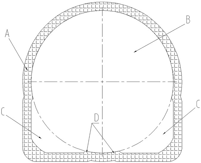
[0065] Here, the tunnel boring machine as a whole includes a main beam extending along the front-to-back direction, and a circular cutter head is arranged at the front end of the main beam to excavate a circular first tunnel section, such as figure 1 In area B in the front shield, auxiliary cutter heads are respectively provided on the inner side of the front shield and on both sides of the bottom of the circular cutter head. The corner area C is excavated, and then the second tunnel section A in the shape of a doorway is formed through the cooperation of the main cutterhead and the auxiliary cutterheads at the bottom of both sides, that is,...

specific Embodiment 2

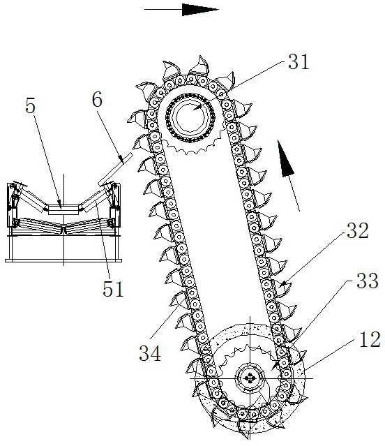
[0078]The main difference between it and Embodiment 1 is that in Embodiment 1, the scraper conveying mechanism includes an upper sprocket, a lower sprocket and a transmission chain. In this embodiment, the scraper conveying mechanism can also adopt the structure of the slag collecting device disclosed in the application publication number CN112727483A, which can include a single driving sprocket and an annular ring arranged around the driving sprocket. Transmission chain, at this moment, the central axis of driving sprocket is parallel with the central axis of central drive shaft, and bucket-shaped hanging plate can be set on the endless transmission chain, satisfy the transshipment of slag.

[0079] Of course, at this time, in order to ensure the normal operation of the screw conveying structure, a separate driving device needs to be provided corresponding to the central drive shaft to drive the central drive shaft to rotate with the helical blades.

specific Embodiment 3

[0081] The difference between it and Embodiment 1 mainly lies in that in Embodiment 1, the lower sprocket is coaxially connected with the central drive shaft, and the central drive shaft is driven to rotate by the corresponding lower sprocket, sharing a motor. In this embodiment, driving motors can be independently configured corresponding to the scraper conveying mechanism and the screw conveying structure, so as to satisfy normal operation.


PUM


Abstract

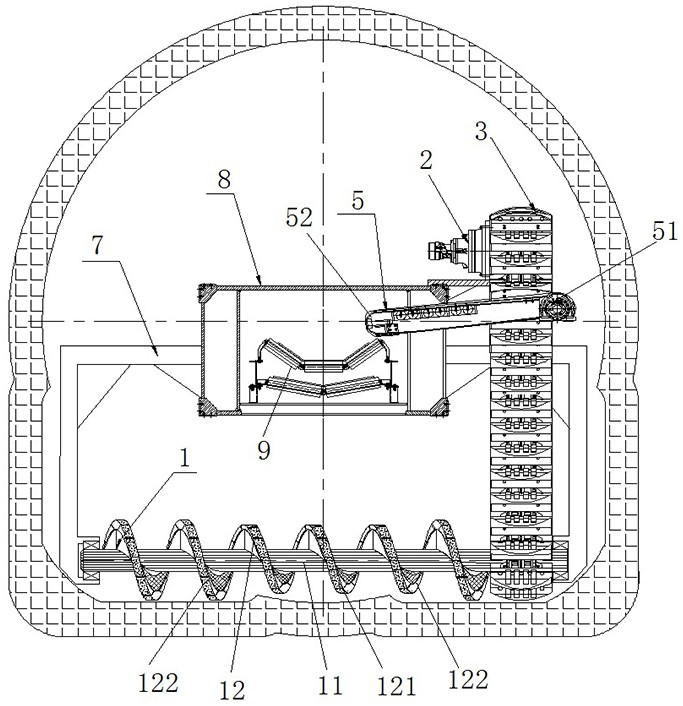
The invention relates to a deslagging device of a tunnel boring machine and the tunnel boring machine. The deslagging device comprises an exposed spiral conveying structure and a scraping plate conveying mechanism; the exposed spiral conveying structure comprises a center driving shaft and a spiral blade; the center driving shaft extends in the horizontal transverse direction corresponding to the width direction of a tunnel, and the spiral blade is fixedly arranged outside the center driving shaft in an exposed mode and extends in the axial direction of the center driving shaft; the axial side of the spiral blade is a discharging side and used for conveying muck at the bottom of the tunnel to the corner area of the bottom of one side of the tunnel; the scraping plate conveying mechanism is correspondingly arranged on the discharging side of the spiral blade; the whole scraping plate conveying mechanism extends in the vertical direction; the scraping plate conveying mechanism is provided with a plurality of scraping plates which are evenly distributed in the circumferential direction of the scraping plate conveying mechanism at intervals; and the scraping plates are used for upwards carrying the muck conveyed by the spiral blade to a main machine belt conveyor of the tunnel boring machine. Due to the fact that the spiral conveying structure is horizontally arranged, scattered muck can be collected in a relatively large range, dead corners of the muck are effectively reduced, and the muck conveying efficiency can be effectively improved.

Description

technical field [0001] The invention relates to a slag discharging device of a tunnel boring machine and the tunnel boring machine. Background technique [0002] The excavation section of the traditional hard rock tunnel boring machine is generally circular, and the rock slag is scooped up into the interior of the cutter head by the slag scraper blade on the circular cutter head, and slides into the main machine along the slag slide plate as the cutter head rotates. The belt conveyor is finally transported to the outside of the cave by the belt conveyor. However, for a tunnel whose full section is a doorway, it is generally excavated through a circular cutterhead and auxiliary tools on both sides to obtain the required section form. [0003] The application publication number is CN112727483A Chinese Invention Patent Application discloses a city gate type tunnel boring machine, the front shield is provided with a main cutter head, which is used to excavate a circular first t...

Claims


Application Information

Patent Timeline
IPC IPC(8): E21D9/12E21D9/10
CPCE21D9/12E21D9/124E21D9/1006
Inventor 叶蕾贺飞肖威陈凯歌宋春晓付玉龙张恒邓飞马永辉赵子辉肖晶娜张朋真赵飞齐志冲
Owner CHINA RAILWAY ENGINEERING EQUIPMENT GROUP CO LTD
Learn More