
Aero-engine fuel system

An aero-engine and fuel system technology, applied in engine components, machines/engines, turbine/propulsion fuel delivery systems, etc., can solve problems such as large power consumption, affect the reliability of other auxiliary equipment, and self-importance, and achieve power consumption. The effect of low volume, reduced power supply equipment, and light weight

Pending Publication Date: 2021-08-06
中科航星科技股份有限公司
View PDF6 Cites 0 Cited by
  • Summary
  • Abstract
  • Description
  • Claims
  • Application Information

AI Technical Summary

Problems solved by technology

[0005] Aiming at the deficiencies in the related technologies, the present invention provides an aero-engine fuel system, which uses the shaft work output of the rotor after the engine starts to provide the power source of the high-pressure oil pump. Reliable oil power, light weight and low power consumption, etc., can solve the technical problems existing in the existing oil supply method, such as large power consumption, affecting the reliability of other auxiliary equipment, and large self-weight

Method used


Image

  • Aero-engine fuel system

Examples


Embodiment Construction

[0039] The technical solutions in the embodiments of the present invention will be clearly and completely described below in conjunction with the drawings in the embodiments of the present invention. Apparently, the described embodiments are only some, not all, embodiments of the present invention. Based on the embodiments of the present invention, all other embodiments obtained by persons of ordinary skill in the art without making creative efforts fall within the protection scope of the present invention.

[0040] In describing the present invention, it should be understood that the terms "center", "transverse", "longitudinal", "upper", "lower", "front", "rear", "left", "right", " The orientations or positional relationships indicated by "vertical", "horizontal", "top", "bottom", "inner" and "outer" are based on the orientations or positional relationships shown in the drawings, and are only for the convenience of describing the present invention and Simplified descriptions...


PUM


Abstract

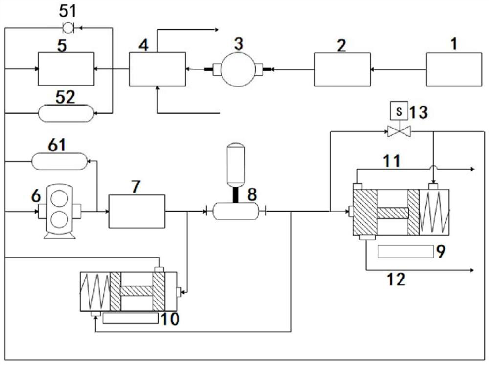
The invention relates to an aero-engine fuel system. The aero-engine fuel system comprises a fuel tank, a low-pressure pump, a high-pressure gear pump, an opening valve, a two-stage filtering device, a fuel regulating valve, an isobaric regulating valve and a main fuel path, wherein the fuel tank is used for storing fuel, the low-pressure pump is connected with the outlet end of the fuel tank through a fuel supply pipeline, the high-pressure gear pump is connected with the outlet end of the low-pressure pump through the fuel supply pipeline, the opening valve is connected with the outlet end of the high-pressure gear pump through the fuel supply pipeline, a first-stage filtering device of the two-stage filtering device is mounted at the front section of the inlet end of the high-pressure gear pump, a second-stage filtering device of the two-stage filtering device is mounted at the front section of the inlet end of the opening valve, the fuel regulating valve is connected with the outlet end of the opening valve through the fuel supply pipeline, the inlet end of the isobaric regulating valve is communicated with the part, between the second-stage filtering device and the inlet end of the opening valve, of the fuel supply pipeline and is used for regulating and controlling the inlet pressure of the opening valve, the outlet end of the isobaric regulating valve is communicated with the part, between the outlet end of the opening valve and the fuel regulating valve, of the fuel supply pipeline and is used for regulating and controlling the outlet pressure of the opening valve, and the main fuel path is connected with the outlet end of the fuel regulating valve through the fuel supply pipeline. The aero-engine fuel system has the characteristics of simple structure, reliable fuel supply power, small dead weight and the like.

Description

technical field [0001] The invention belongs to the technical field of aero-engines, in particular to an aero-engine fuel system. Background technique [0002] For aeroengines, the fuel system is an important component system. Its main function is to continuously provide stable quality fuel for combustion. Fuel combustion converts chemical energy into mechanical energy and heat energy to form high-temperature and high-pressure gas. After the gas enters the turbine Expansion work, part of the expansion work is transmitted to the compressor through the transmission shaft, and the other part is output to the outside, as a power device for fighter jets, missiles, unmanned aerial vehicles, etc. [0003] At present, the main fuel supply method for aero-engines is electric gear pump fuel supply, but when this fuel supply method requires high-pressure fuel supply, it has large power consumption, high current, easy to form electromagnetic interference, and reduces the use of other at...

Claims


Application Information

Patent Timeline
Patent Type & Authority Applications(China)
IPC IPC(8): F02C7/232F02C7/236F02C6/00F02C9/26F02C9/28
CPCF02C7/236F02C7/232F02C6/00F02C9/263F02C9/28F02C9/26
Inventor 张伟黄迪兰佳哲潘武义潘庆伟杨宇超丁浩肖玉坤丁金龙孙世权刘迪黄安琦宋收徐超豪王帅杜涛杨晓洁曹浩波
Owner 中科航星科技股份有限公司
Learn More