
Centrifugal permanent magnet automatic clutch combining friction and synchronous locking
An automatic clutch, synchronous locking technology, applied in the direction of automatic clutch, magnetic drive clutch, non-mechanical drive clutch, etc., can solve the problem of insufficient coupling force, and achieve the effect of low separation speed, high coupling speed, and fast clutch transition.
- Summary
- Abstract
- Description
- Claims
- Application Information
AI Technical Summary
Problems solved by technology
Method used
Image

Examples
Embodiment Construction
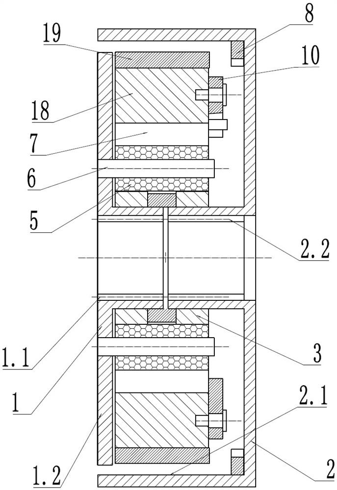
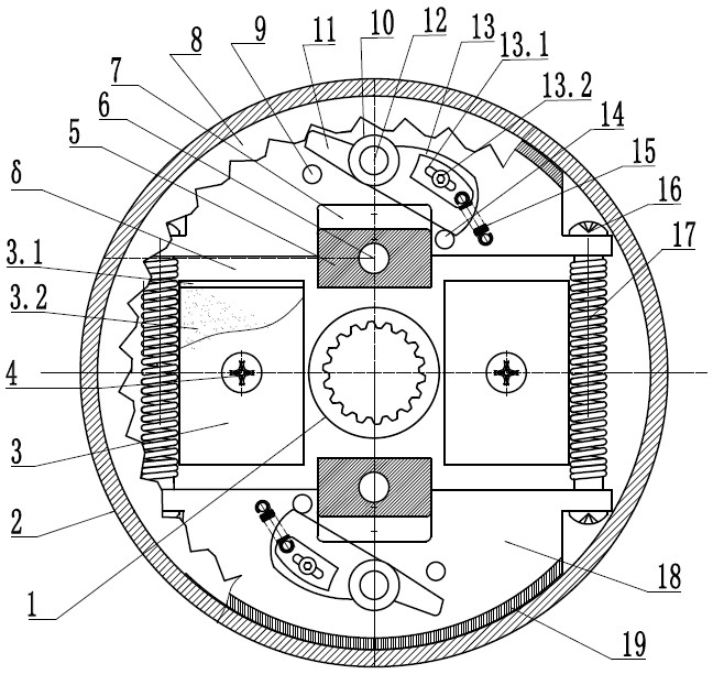
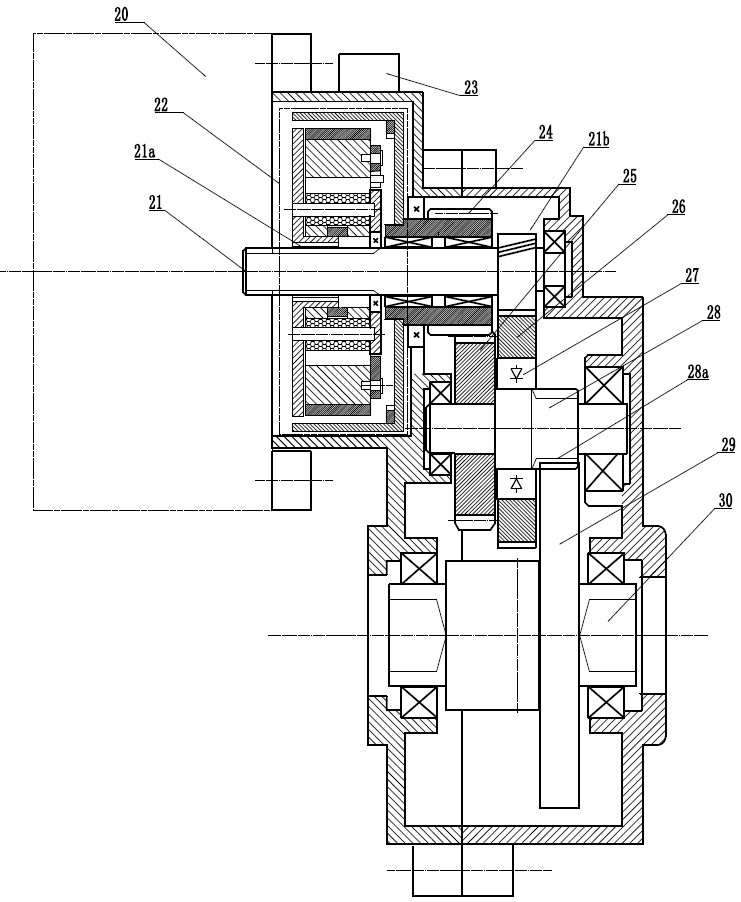
[0026] This example is one of the specific configurations of the present invention for further explanation of the invention. figure 2 . This example is the active end, the connection power input, the B-terminal is a driven end, connected to the load end. This example is symmetrically configured between the A end and the B end. Two sets of clutch mechanisms are provided. You can also set up 3 groups or more.
[0027]The A terminal is composed of 1.2 bottom plate and 1.1 connecting portion A. There is a pin 6 on the bottom plate, and the buffer member is a buffer 5, and the buffer 5 is connected to the pin 6, and the buffer body is made of an elastic damping material. A slot 7 is provided on the centrifugal block 18, fitted to the buffer body, movable radial, and transmitting torque at the same time. The circular arc surface of the heart is connected to the Mochi 19. The separation spring 17 is a tensile spring that is coupled between the two sets of centrifugal blocks with a connec...
PUM
 Abstract
Description
Claims
Application Information