
Particle removing device

A technology for removing devices and particulate matter, applied in boiler cleaning devices, steam separation devices, etc., can solve the problems of valve pipe and steam turbine blade wear, unit overspeed, threatening unit safety, etc., to prevent jamming, simple structure, and prevent overspeed. Effect

Pending Publication Date: 2021-08-06
XIAN THERMAL POWER RES INST CO LTD
View PDF0 Cites 0 Cited by
  • Summary
  • Abstract
  • Description
  • Claims
  • Application Information

AI Technical Summary

Problems solved by technology

The solid particles in the steam will not only wash away the valve pipes and steam turbine blades to cause wear, but also often cause jamming of steam turbine regulating valves, etc.
The jamming of the regulating valve of the steam turbine will affect the normal closing of the steam valve of the unit. When necessary, the steam entering the steam turbine cannot be effectively cut off, and there is a safety hazard causing the unit to overspeed, threatening the safety of the unit.

Method used


Image

  • Particle removing device
  • Particle removing device

Examples


Embodiment Construction

[0019] The present invention will be described in detail below in conjunction with the accompanying drawings.

[0020] In describing the present invention, it should be understood that the terms "center", "longitudinal", "transverse", "length", "width", "thickness", "upper", "lower", "front", " Back", "Left", "Right", "Vertical", "Horizontal", "Top", "Bottom", "Inner", "Outer", "Clockwise", "Counterclockwise", "Axial", The orientation or positional relationship indicated by "radial", "circumferential", etc. is based on the orientation or positional relationship shown in the drawings, and is only for the convenience of describing the present invention and simplifying the description, rather than indicating or implying the referred device or element Must be in a particular orientation, be constructed in a particular orientation, and operate in a particular orientation, and therefore should not be construed as limiting the invention.

[0021] In the present invention, terms such...


PUM


Abstract

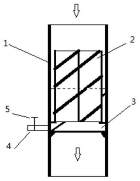
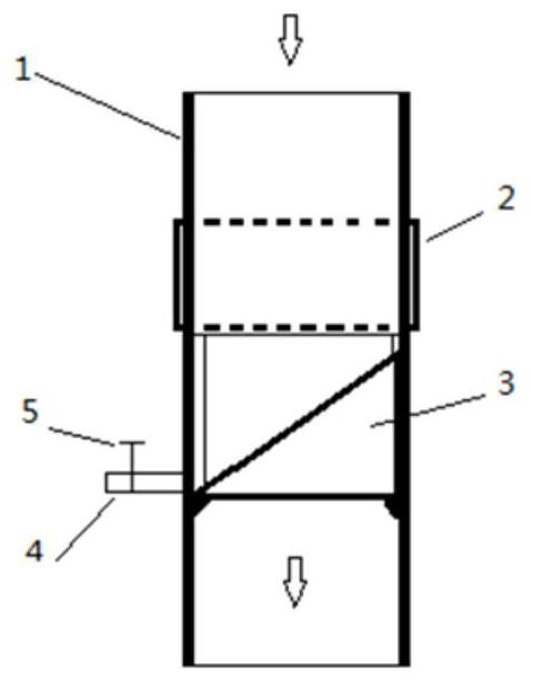
A particle removing device comprises a separator and a collecting device which are arranged in a steam pipeline, and the separator is connected with the collecting device. A discharging pipe is arranged on the collecting device, a valve is arranged on the discharging pipe, and the discharging pipe is located outside the steam pipeline. According to the particle removing device, solid particles in steam can be prevented from scouring a valve pipeline and turbine blades and causing abrasion, the solid particles in the steam can be prevented from causing jamming of a turbine adjusting valve and the like, and it is guaranteed that the turbine adjusting valve and the like can be normally closed when needed so as to effectively cut off steam entering a turbine, prevent the overspeed of a unit and ensure the safety of the unit.

Description

technical field [0001] The invention belongs to the field of thermal power generation, and in particular relates to a particle removal device. Background technique [0002] In order to improve the cycle efficiency of thermal power units, the steam parameters of power plant boilers have been continuously improved. At present, they have reached ultra-supercritical parameters, and the steam temperature has reached 600°C-620°C, which is close to the limit of the metal service temperature. Due to the increase of steam parameters, the problem of steam oxidation of metal pipes is becoming more and more prominent. The metal is oxidized by steam to form an oxide scale. With the increase of use time, the oxide scale thickens and falls off, and solid particles enter the steam. The solid particles in the steam will not only wash away the valve pipes and steam turbine blades to cause wear, but also often cause jamming of steam turbine regulating valves, etc. The jamming of the regulati...

Claims


Application Information

Patent Timeline
Patent Type & Authority Applications(China)
IPC IPC(8): F22B37/32F22B37/54
CPCF22B37/32F22B37/54
Inventor 党黎军沈植张良平姚惠珍杨辉柯于进郭俊文
Owner XIAN THERMAL POWER RES INST CO LTD
Learn More