Channel estimation method and system based on positioning information assistance

A positioning information and channel estimation technology, applied in the field of channel estimation based on positioning information, can solve the problems of increasing channel pilot overhead, unable to send, receive or process pilot signal channel estimation, etc., to reduce time complexity and Effects of time and complexity, optimized size and precision

Active Publication Date: 2021-08-06
HANGZHOU DIANZI UNIV
View PDF6 Cites 9 Cited by
  • Summary
  • Abstract
  • Description
  • Claims
  • Application Information

AI Technical Summary

Problems solved by technology

First, all RIS components are passive, it cannot transmit, receive or process any pilot signals for channel estimation
Second, since a RIS usually consists of hundreds of el

Method used


Image

  • Channel estimation method and system based on positioning information assistance
  • Channel estimation method and system based on positioning information assistance
  • Channel estimation method and system based on positioning information assistance

Examples


Embodiment 1

[0142] A channel estimation method based on positioning information assistance in an RIS system under an Internet of Vehicles environment, specifically comprising the following steps:

[0143] Step 1: Obtain the relative position information of the object in the communication based on the Internet of Vehicles system, first initialize the relative position of the sending end, the intelligent reflector and the receiving end, and set

[0144] BS:(x 1 ,y 1 ,z 1 )

[0145] RIS:(x 2 ,y 2 ,z 2 )

[0146] User:(x 3 ,y 3 ,z 3 )

[0147] Wherein, the set coordinates are the center point positions of the corresponding communication devices.

[0148] Step 2: According to the obtained relative positions of the base station, RIS and receiving end, the azimuth and elevation angles of the BS can be calculated as:

[0149]

[0150]

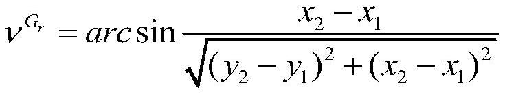
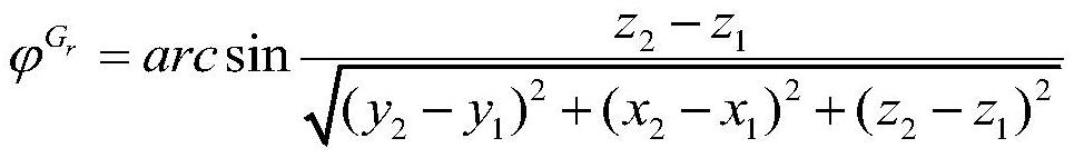
[0151] The azimuth and elevation angles of the RIS received signal are:

[0152]

[0153]

[0154] The azimuth and elevation angles of th...

Embodiment 2

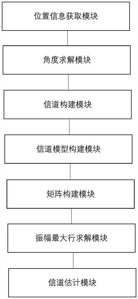
[0201] Such as figure 1 As shown, a channel estimation system based on positioning information in the RIS system in the Internet of Vehicles environment, specifically includes the following modules:

[0202] Position Information Acquisition Module: Obtain the relative position information of objects in communication based on the Internet of Vehicles system, first initialize the relative positions of the sending end, the intelligent reflective surface and the receiving end, and set

[0203] BS:(x 1 ,y 1 ,z 1 )

[0204] RIS:(x 2 ,y 2 ,z 2 )

[0205] User:(x 3 ,y 3 ,z 3 )

[0206] Wherein, the set coordinates are the center point positions of the corresponding communication devices.

[0207] Angle solution module: According to the obtained relative positions of the base station, RIS and receiving end, the azimuth and elevation angles of the BS can be calculated as follows:

[0208]

[0209]

[0210] The azimuth and elevation angles of the RIS received signal ar...


PUM


Abstract

The invention discloses a channel estimation method and system based on positioning information assistance in an RIS system in an Internet of Vehicles environment, and the method comprises the following steps: obtaining the relative position information of a base station, an intelligent reflection surface, namely an RIS, and a vehicle based on the Internet of Vehicles system; obtaining the azimuth angle and the elevation angle of the effective signal in the line-of-sight propagation process from the base station to the RIS and from the RIS to the receiving end; constructing a cascade channel G from the base station to the RIS and a cascade channel hr, k from the RIS to the receiving end, and solving a cascade channel Hk; constructing a channel model, and constructing an overall measurement matrix Hk of Q time slots; writing Hk into a CS model according to an angular domain cascade channel, constructing a new dictionary matrix D according to azimuth angles and elevation angles of received signals and reflected signals, and constructing a new sensing matrix Aq=(D*theta'q)H; setting a signal received by the receiving end as an initialized residual vector r0, calculating the correlation between the sensing matrix A and the residual vector r0, and obtaining a row row * with the maximum amplitude according to the correlation; and according to the obtained row *, obtaining a sparse vector of an estimation channel H through an LS algorithm, and updating a residual vector to obtain the estimation channel.

Description

technical field [0001] This patent belongs to the technical field of RIS (smart surface) assisted communication channel estimation technology in the Internet of Vehicles environment, and particularly relates to a channel estimation method and system based on positioning information in the RIS system in the Internet of Vehicles environment. Background technique [0002] In recent years, reconfigurable smart surfaces (RIS) have been proposed to improve the coverage and capacity of wireless communication systems with low hardware cost and energy consumption. The RIS concept is based on controlling the propagation of electromagnetic waves in a communication channel to improve the performance of the communication system. Specifically, the IRS is a metasurface composed of several microfacets that can control the phase of the incident signal. Ideally, the controlled phase would be continuous, but metasurfaces approximate this using several discrete "elements" of subwavelength size...

Claims


Application Information

Patent Timeline
IPC IPC(8): H04L25/02H04W4/40H04B7/145
CPCH04L25/0242H04L25/0224H04W4/40H04B7/145
Inventor 曾嵘杭潇邵智敏包建荣
Owner HANGZHOU DIANZI UNIV
Why Eureka
Try Eureka