Water dispenser shell capable of preventing static electricity and facilitating layered disassembly and maintenance
A technology to prevent static electricity and water dispensers, applied in the direction of static electricity, electrical components, beverage preparation devices, etc., can solve the problems of the user's water connection work, easy to appear static electricity, and take a lot of time for disassembly and maintenance, etc., to achieve the elimination of static electricity, Improve the effect of antistatic function
- Summary
- Abstract
- Description
- Claims
- Application Information
AI Technical Summary
Problems solved by technology
Method used
Image
Examples
Embodiment 1
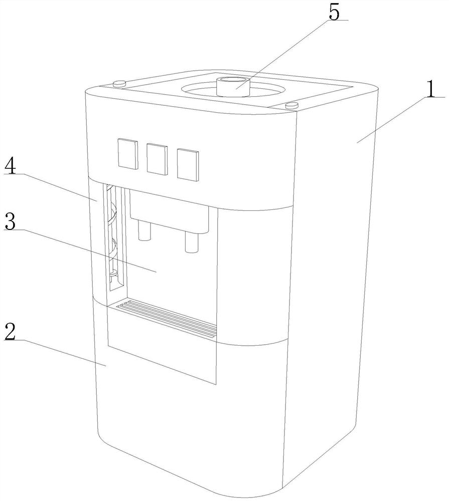
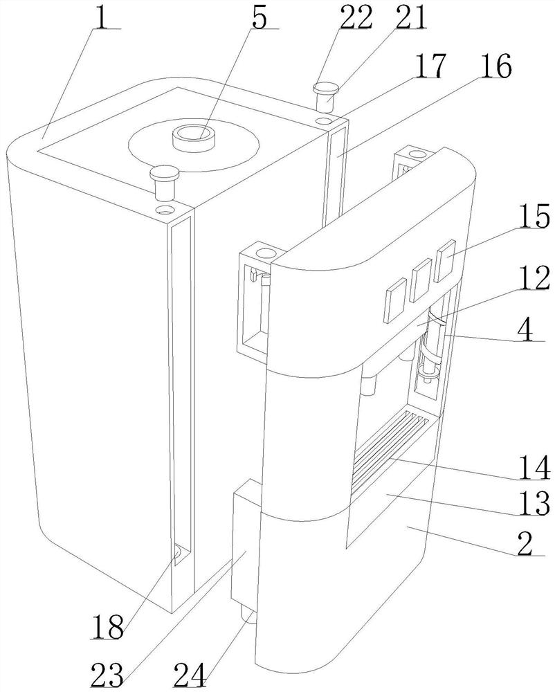
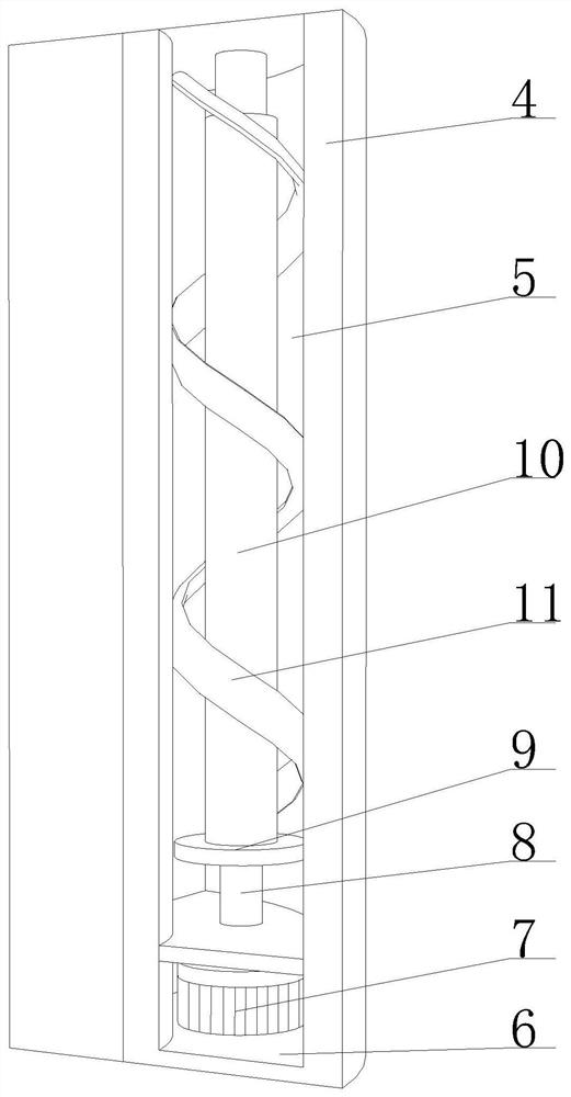
[0038] Such as Figure 1-6 As shown, the present invention provides a water dispenser shell that can prevent static electricity and facilitate layered disassembly and maintenance, including a main shell 1 and a mobile shell 2 arranged in front of it, and a water receiving cavity is opened on the front of the mobile shell 2 3. The left and right ends of the inner wall of the water receiving chamber 3 are embedded with antistatic mechanisms 4, which can prevent static electricity and facilitate the layered disassembly and maintenance of the water dispenser shell. When in use, the water receiving work can be carried out inside the water receiving chamber 3, and this Simultaneously, the antistatic mechanism 4 operates at both ends of the inner wall of the water receiving cavity 3 .
[0039] The inner side of the antistatic mechanism 4 is provided with a circulation groove 5, the inner wall bottom of the circulation groove 5 is provided with a fixed groove 6, and the inner wall bot...
Embodiment 2
[0042] Such as Figure 1-6As shown, on the basis of Embodiment 1, the present invention provides a technical solution: preferably, the left and right ends of the front of the main housing 1 are provided with fixing grooves 16, and the top of the inner wall of the fixing groove 16 is provided with positioning Slot one 17, positioning groove one 17 runs through the top of the main housing 1, the top left and right ends of the back of the mobile housing 2 are provided with top fixing brackets 19, and the bottom left and right ends of the back of the mobile housing 2 are all provided with bottom fixing brackets. Frame 23, top fixed frame 19, bottom fixed frame 23 are all detachably connected with the inwall of fixed groove 16, and the top of top fixed frame 19 is all provided with the positioning groove two 20 that matches with positioning groove one 17, when main housing 1 When connecting with the mobile housing 2, the top fixing frame 19 and the bottom fixing frame 23 provided o...
Embodiment 3
[0046] like Figure 1-6 As shown, on the basis of Embodiment 1, the present invention provides a technical solution: preferably, the left and right ends of the inner side of the top fixing frame 19 are movably connected with a clamping magnetic ring 26 by being provided with a connecting spring 25, and the clamping magnetic ring 26 is movably connected. The magnetic pole distribution of the ring 26 and the limit magnet 21 is opposite to each other. After the limit magnet 21 is located in the groove two 20, its inside is positioned at the inner side of the top fixing frame 19, and is magnetically connected with the clamping magnetic ring 26 in its inner side. , under the elastic action of the connecting spring 25, the clamping magnetic ring 26 can be stably and effectively clamping the limit magnetic block 21 to prevent it from falling off, and it is also convenient for the main housing 1 and the moving housing 2 The connection is fixed.
[0047] The top of the inner wall of t...
PUM
 Abstract
Description
Claims
Application Information
 - R&D
- Intellectual Property
- Life Sciences
- Materials
- Tech Scout
- Unparalleled Data Quality
- Higher Quality Content
- 60% Fewer Hallucinations
Browse by: Latest US Patents, China's latest patents, Technical Efficacy Thesaurus, Application Domain, Technology Topic, Popular Technical Reports.
© 2025 PatSnap. All rights reserved.Legal|Privacy policy|Modern Slavery Act Transparency Statement|Sitemap|About US| Contact US: help@patsnap.com


