Conveying machine table connecting device

A conveyor and conveying direction technology, which is applied to conveyor control devices, conveyors, mechanical conveyors, etc., can solve the problems of difficult installation of folding cylinders, hidden safety hazards for personnel, and large space for folding mechanisms, and achieves simple structure and movement. The effect of simplified stroke and simplified mechanical structure

Pending Publication Date: 2021-08-10
JA SOLAR
View PDF8 Cites 0 Cited by
  • Summary
  • Abstract
  • Description
  • Claims
  • Application Information

AI Technical Summary

Problems solved by technology

However, due to the limited space between the conveying machines and the large space required for the folding mechanism, it is difficult to install the folding cylinder; at the same time, the cylinder uses compressed air as the air source. If the air source is interrupted, the folding cylinder retracts, which will cause passageway Sudden closure, causing safety hazards to passers-by

Method used


Image

  • Conveying machine table connecting device
  • Conveying machine table connecting device

Examples


Embodiment Construction

[0025] Reference will now be made in detail to the exemplary embodiments, examples of which are illustrated in the accompanying drawings. When the following description refers to the accompanying drawings, the same numerals in different drawings refer to the same or similar elements unless otherwise indicated. The implementations described in the following exemplary embodiments do not represent all implementations consistent with this application. Rather, they are merely examples of methods and apparatus consistent with aspects of the present application as recited in the appended claims.

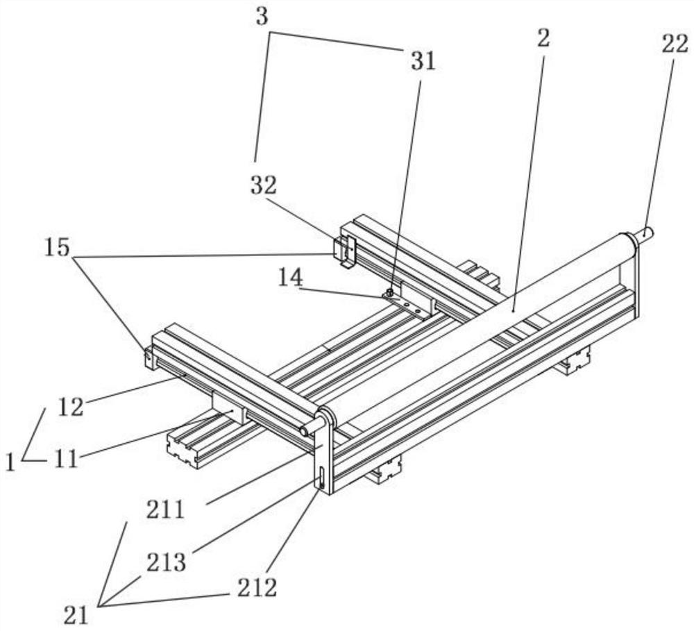
[0026] Such as figure 1 As shown, this embodiment provides a connecting device for conveying machines, which is arranged between two conveying machines arranged at intervals in the assembly line, and includes: a push-pull mechanism 1, a roller shaft 2 and a switch, wherein the push-pull mechanism 1 has Guide block 11 and slide track 12, guide block 11 is arranged on any conveying machine ...


PUM


Abstract

The invention relates to the field of photovoltaic production equipment, and provides a conveying machine table connecting device. The device comprises a push-pull mechanism, a roll shaft and a switch; the push-pull mechanism is provided with a guide block and a sliding rail, the guide block is arranged on any conveying machine table and used for providing a mounting site for the sliding rail, and the sliding rail is arranged on the guide block in a sliding mode in the conveying direction of an assembly line so as to connect two adjacent conveying machine tables or avoid a channel between the two adjacent conveying machine tables; the roller shaft is erected on the sliding rail, and the conveying direction of the roller shaft is the same as the conveying direction of the assembly line, so that materials are continuously conveyed between the two adjacent conveying machine tables; and the switch is used for controlling shutdown or operation of the assembly line according to the position of the sliding rail. The device is small in occupied space, convenient to operate and good in connection effect.

Description

technical field [0001] The invention relates to the field of photovoltaic production equipment, in particular to a connecting device for a conveyor machine. Background technique [0002] The assembly line is one of the most basic equipment of photovoltaic modules. It not only runs through the equipment, but also serves as a bridge connecting other equipment. During the automatic transportation of components, the assembly line is formed by successively connecting conveyors one by one, and due to the needs of production, it is also necessary to set up logistics channels or safety channels on the assembly line. Therefore, how to connect the gaps or passages between conveyor machines is a problem that needs to be considered in daily production. [0003] At present, most of the gaps between conveying machines, required logistics channels and safety channels are closed by folding cylinders. However, due to the limited space between the conveying machines and the large space requ...

Claims


Application Information

Patent Timeline
IPC IPC(8): B65G43/08B65G47/64B65G35/00B65G47/24
CPCB65G43/08B65G47/642B65G35/00B65G47/24B65G2203/044
Inventor 周江泽李骏邓浩
Owner JA SOLAR
Why Eureka
Try Eureka