Yarn twisting and winding robot
A robot and twisting technology, applied in the field of robots, can solve the problems of slow semi-automatic yarn winding operation, affecting the progress of yarn feeding and yarn feeding, and sluggish work cycle, so as to improve the uniformity of storage and storage, and ensure the balance of wire arrangement , Guarantee the effect of flexible adjustment
- Summary
- Abstract
- Description
- Claims
- Application Information
AI Technical Summary
Problems solved by technology
Method used
Image
Examples
Embodiment 1
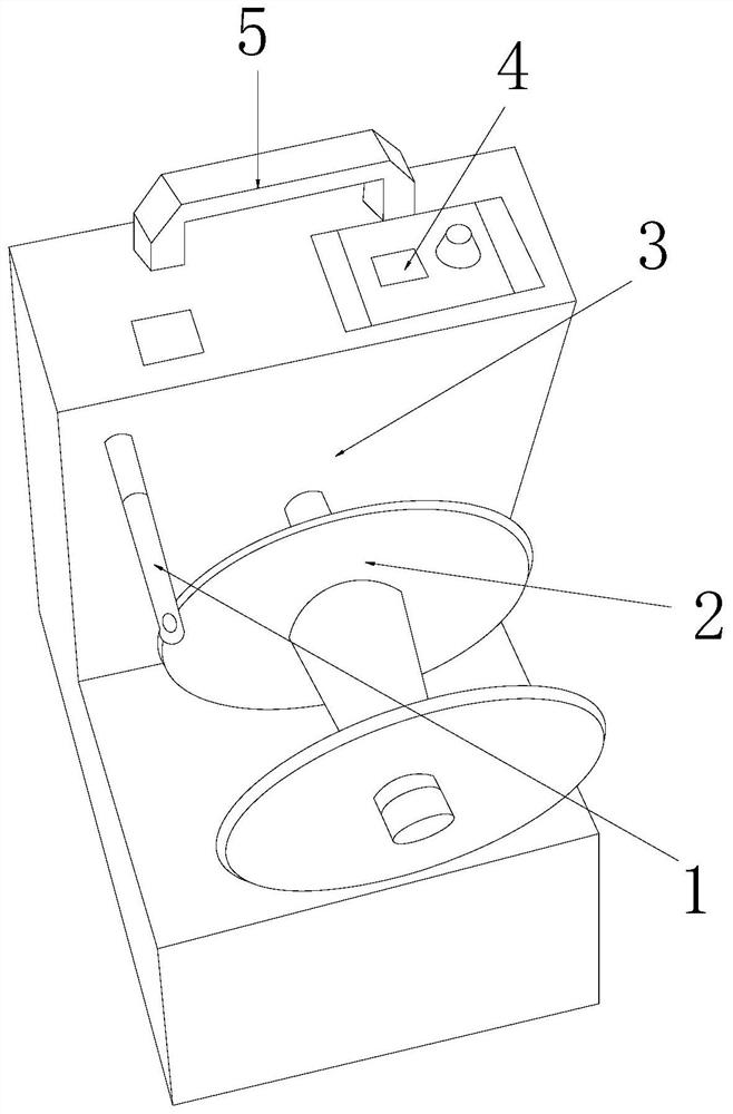
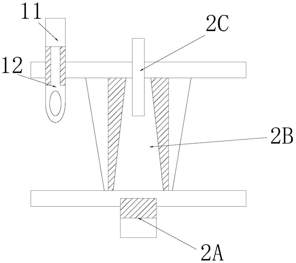
[0035] see Figure 1-Figure 8 , the present invention provides a kind of twisting yarn winding robot, and its structure comprises: Twisting needle rack 1, yarn winding shaft pusher frame 2, clamping shaft motor box 3, industrial control panel 4, handle pull bar 5, described yarn winding shaft The pusher frame 2 is mechanically connected with the clamp shaft motor box 3, the twisting needle frame 1 is installed on the upper left corner of the yarn winding shaft push tube frame 2 and is parallel to each other, and the industrial control panel 4 is closely attached to the clamp shaft motor box 3 On the top surface and on the same horizontal plane, the handle bar 5 and the clamp shaft motor box 3 are inserted together and are perpendicular to each other, and the yarn winding shaft pushing frame 2 is arranged on the front side of the clamp shaft motor box 3 and The shaft centers are collinear, and the yarn winding shaft pushing frame 2 is provided with a yarn pressing shaft column ...
Embodiment 2
[0043] see Figure 1-Figure 8 , the present invention provides a kind of twisted yarn winding robot, other respects are identical with embodiment 1, and difference is:
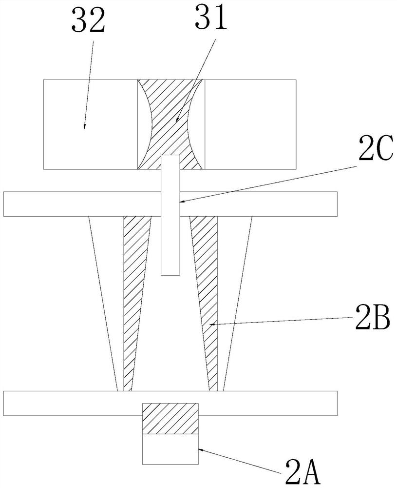
[0044] see image 3 , the clamp shaft motor box 3 is composed of a clamp shaft bundle sleeve 31 and a motor case 32, the clamp shaft bundle sleeve 31 is installed inside the motor case 32, and the clamp shaft bundle sleeve 31 passes through the motor and the motor case 32 is mechanically connected, and the motor is axially connected to the motor in the motor case 32 through the clamping shaft bundle sleeve 31 to form the operation effect of locking the shaft.
[0045] see Image 6 , the clamp shaft beam sleeve 31 is composed of a clamp shaft petal seat block 311 and a beam sleeve 312, and two clamp shaft petal seat blocks 311 are installed on the left and right sides of the beam sleeve 312 respectively. The clamping shaft petal seat block 311 and the beam sleeve 312 are inserted and embedded together and ar...
PUM
 Abstract
Description
Claims
Application Information
 - R&D
- Intellectual Property
- Life Sciences
- Materials
- Tech Scout
- Unparalleled Data Quality
- Higher Quality Content
- 60% Fewer Hallucinations
Browse by: Latest US Patents, China's latest patents, Technical Efficacy Thesaurus, Application Domain, Technology Topic, Popular Technical Reports.
© 2025 PatSnap. All rights reserved.Legal|Privacy policy|Modern Slavery Act Transparency Statement|Sitemap|About US| Contact US: help@patsnap.com


