Supercharge Your Innovation With Domain-Expert AI Agents!

Shield shaft ell end large pipe shed structure based on double-layer lining and construction method

A technology for shield wells and large pipe sheds, which is applied in shaft lining, tunnel lining, shaft equipment, etc., and can solve the problems of failure to meet environmental protection requirements around shield wells, structural waterproof requirements, and penetration of shield well end walls, etc. problems, to avoid unstable factors, high economic and social benefits, and low construction costs

Pending Publication Date: 2021-08-10
POWERCHINA XIBEI ENG
View PDF0 Cites 0 Cited by
  • Summary
  • Abstract
  • Description
  • Claims
  • Application Information

AI Technical Summary

Problems solved by technology

Under normal conditions, the large pipe shed is erected after the main structure of the shield tunnel is constructed. However, since the large pipe shed is located above the shield tunnel door and at the end wall of the shield tunnel, the construction of the pipe shed will cause the end wall of the shield tunnel to be damaged. Breaking through and smashing will not only fail to meet the waterproof requirements of the structure, but also leave a huge safety hazard and potential risk, and it will not be able to meet the environmental protection requirements around the shield well

Method used


Image

  • Shield shaft ell end large pipe shed structure based on double-layer lining and construction method
  • Shield shaft ell end large pipe shed structure based on double-layer lining and construction method
  • Shield shaft ell end large pipe shed structure based on double-layer lining and construction method

Examples


Embodiment 1

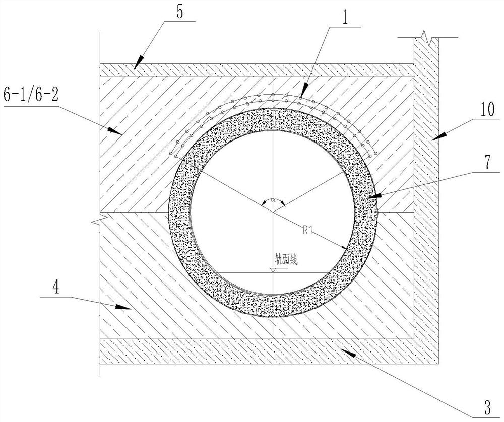
[0036] refer to Figure 1-Figure 4 A large pipe shed structure at the end of a shield well based on double-layer lining is shown, including a large pipe shed 1, a pipe shed guide pipe 2, a shield well bottom plate 3, a shield downhole end wall 4, a shield well mid-plate 5, The upper end wall of the shield tunnel, the shield tunnel 7, the post-cast ring beam 8 of the shield tunnel door, and the side wall 10 of the shield tunnel; the bottom of the shield tunnel 7 is provided with a shield tunnel bottom plate 3, The upper part of the end of the tunnel 7 is provided with a shield well plate 5, and a shield well side wall 10 is provided on one side of the shield well center plate 5 and the shield well bottom plate 3; a shield well end is provided at the end of the shield tunnel 7 The shield shaft end wall is composed of the shield tunnel end wall 4 and the shield tunnel upper end wall, the shield shaft upper end wall is located at the upper part of the shield tunnel end wall 4, and...

Embodiment 2

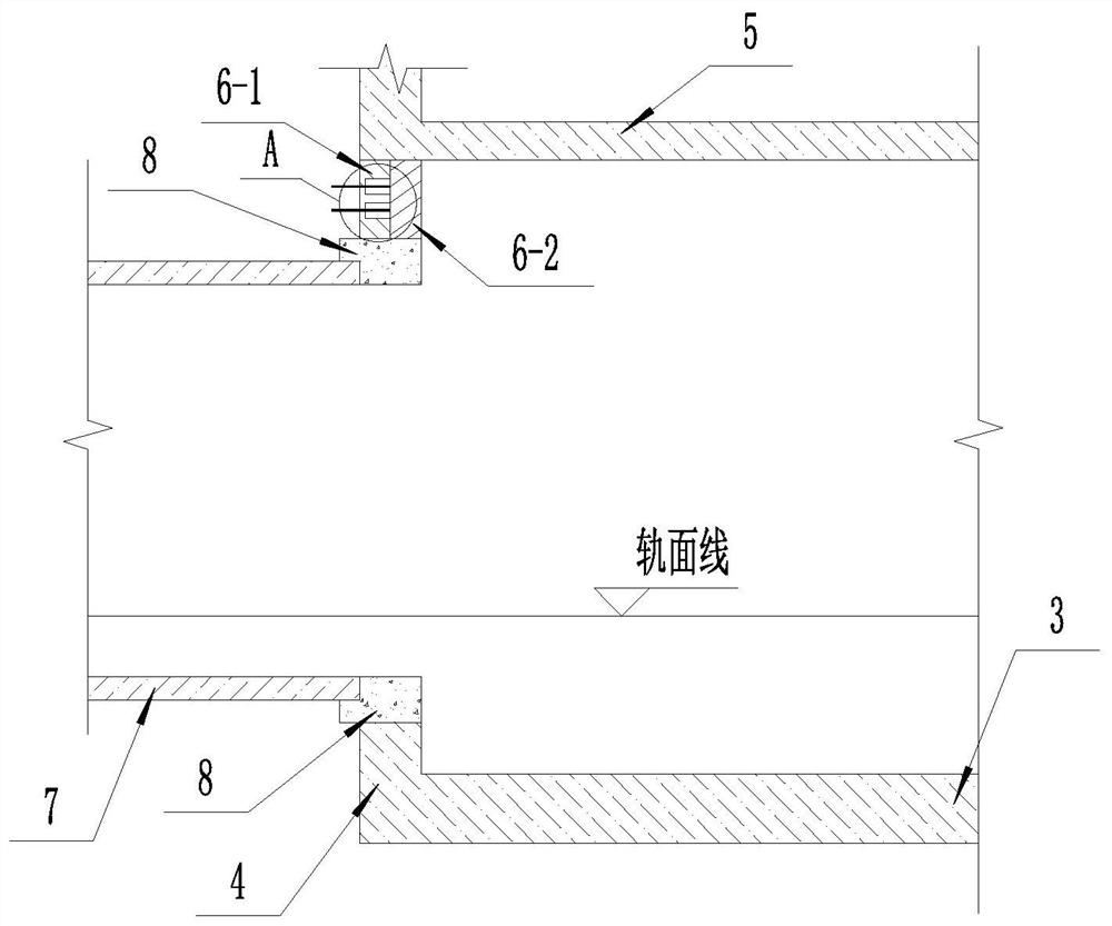
[0042] refer to figure 1 and Figure 4 The shown one based on the double-layer lining of the large pipe shed structure at the end of the shield well is different from the first embodiment in that: the two sides of the pipe shed guide pipe 2 are provided with pipe shed guide pipe positioning steel bars 9, and the pipe shed The guide pipe positioning steel bar 9 is connected with the main reinforcement in the shield tunnel end wall 4 and the shield tunnel upper end outer wall 6-1.

[0043] The adoption of the technical solution in actual use makes the structure of the present invention have a higher degree of integration, better stability, and ensures controllable precision of laying large pipe sheds.

Embodiment 3

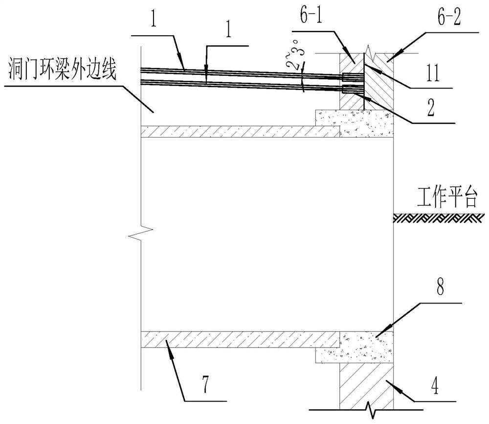
[0045] refer to figure 1 and image 3 The shown one based on the double-layer lining of the large pipe shed structure at the end of the shield well is different from the first embodiment in that: the pipe shed guide pipe 2 is arranged in an arc shape, and the number of rows is not less than two .

[0046] Preferably, the pipe shed guide pipe 2 is arranged within the range of 120°-150° of the arch portion directly above the shield tunnel 7, with a circumferential distance of 0.3m-0.4m.

[0047] In actual use, the pipe shed guide pipe 2 adopts this technical solution, which not only meets the stability requirements of the present invention, but also can ensure that the laying accuracy of the large pipe shed is controllable,


PUM

PropertyMeasurementUnit
Wall thicknessaaaaaaaaaa

Abstract

The invention belongs to the technical field of tunnel engineering shield shafts, and particularly relates to a shield shaft end large pipe shed structure based on a double-layer lining and a construction method. According to the shed structure, a large pipe shed, a pipe shed guide pipe, a shield shaft bottom plate, a shield shaft lower end wall, a shield shaft middle plate, a shield shaft upper end wall composed of a shield shaft upper end outer side wall and a shield shaft upper end inner side wall, a shield tunnel, a shield shaft portal post-pouring ring beam and a shield shaft side wall are organically combined, and the shed structure is constructed through eight steps. According to the shield shaft upper end wall of the double-layer structure form, the shield shaft upper end outer side wall meets the requirements for large pipe shed driving positioning and precision control, the shield shaft upper end inner side wall meets the requirements for structure waterproof and overall stability, large pipe shed stratum reinforcement is effectively separated from a structure waterproof and stress system, so that requirements of surrounding environment protection on large pipe shed driving precision and disturbance control can be met, the structure safety and stability control target can be achieved, and the structure has wide application prospects.

Description

technical field [0001] The invention belongs to the technical field of shield tunneling engineering, and in particular relates to a double-layer lining-based large pipe shed structure at the end of a shield well and a construction method. Background technique [0002] For the current rail transit projects in major cities in China, with the encryption of the subway network and the continuous improvement of the surrounding environmental protection requirements, the requirements for construction technology are also getting higher and higher. As one of the most important and difficult points of the shield tunneling project, The construction of shield access tunnels has always been the focus of attention, especially in water-rich formations and relatively harsh surrounding environments. Under normal conditions, the large pipe shed is erected after the main structure of the shield tunnel is constructed. However, since the large pipe shed is located above the shield tunnel door and...

Claims


Application Information

Patent Timeline
IPC IPC(8): E21D9/14E21D11/00E21D11/10E21D11/38E21F17/103
CPCE21D9/14E21D11/003E21D11/10E21D11/38E21F17/103
Inventor 柳兴旺高徐军戴志仁尉甜甜韩文斌白鹤马高峰孙茉秦青阳查亚辉薛旋俱军涛
Owner POWERCHINA XIBEI ENG
Features
  • R&D
  • Intellectual Property
  • Life Sciences
  • Materials
  • Tech Scout
  • Unparalleled Data Quality
  • Higher Quality Content
  • 60% Fewer Hallucinations
Learn More