
Steam turbine for dry quenching waste heat power generation

A waste heat power generation and steam turbine technology, which is applied to engine components, machines/engines, mechanical equipment, etc., can solve problems such as high viscosity and difficult formation of oil film, and achieve the effect of improving lubrication effect, increasing service life and reasonable structure

Active Publication Date: 2021-08-10
丰城市天壕新能源有限公司
View PDF14 Cites 0 Cited by
  • Summary
  • Abstract
  • Description
  • Claims
  • Application Information

AI Technical Summary

Problems solved by technology

[0007] The purpose of this application is to provide a steam turbine for coke CDQ waste heat power generation, which can intelligently identify the temperature and viscosity of the lubricating oil in the bearing oil chamber, effectively solving the problem of steam turbine When starting, the temperature of the lubricating oil is low, which makes the viscosity high and the oil film is difficult to form, which improves the lubricating effect of the lubricating oil on the bearing, and is heated by steam without adding other heating systems, which reduces the manufacturing cost. The cooling water cools the lubricating oil, fully utilizes the energy in the CDQ waste heat power generation system, and realizes the switching between the lubricating oil that must be replaced and the new lubricating oil when there are many impurities. On the one hand, it improves the production efficiency and improves the bearing life. On the other hand, there is no need for manual monitoring and identification at all times, which saves labor

Method used


Image

  • Steam turbine for dry quenching waste heat power generation
  • Steam turbine for dry quenching waste heat power generation
  • Steam turbine for dry quenching waste heat power generation

Examples


Embodiment

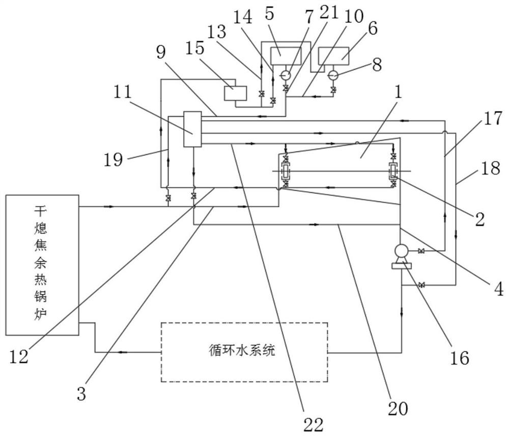
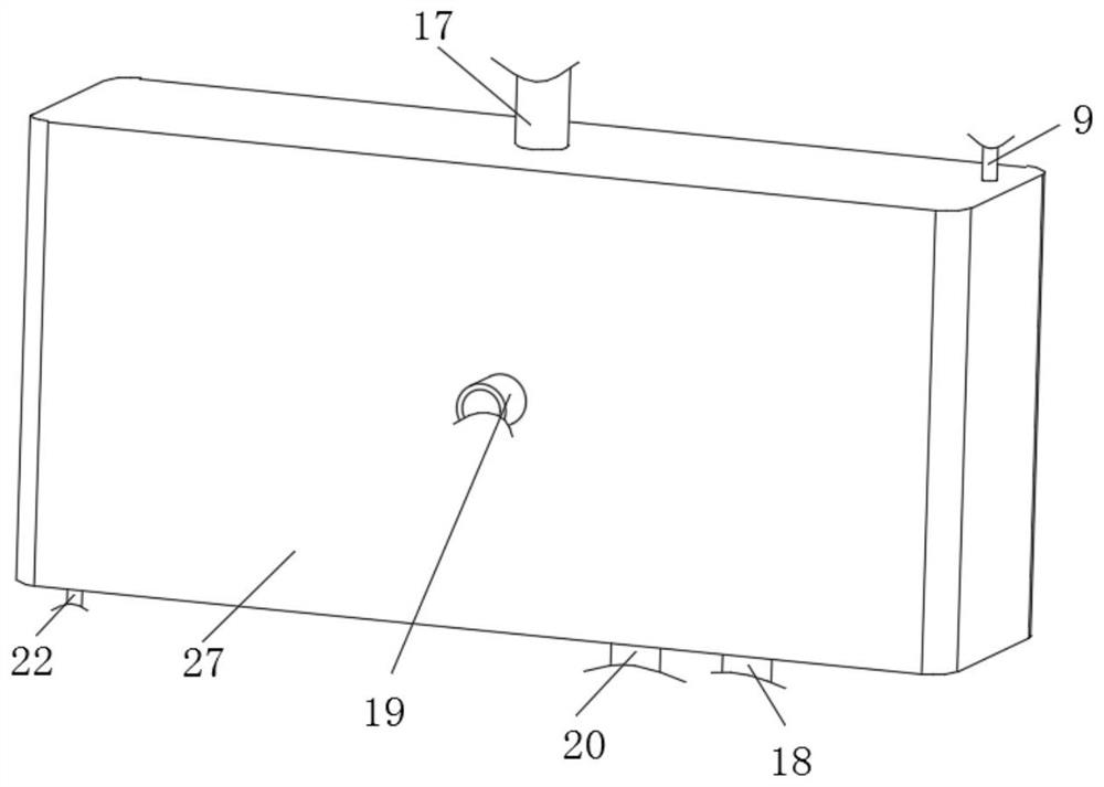
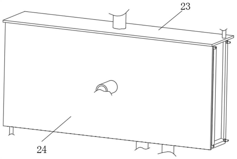
[0033] Example: Reference Figure 1-4 A steam turbine for CDQ waste heat power generation as shown includes a steam turbine 1, a bearing 2 installed on the rotating shaft of the steam turbine 1, and the bearing 2 is installed on the cylinder block of the steam turbine 1 through a bearing bush and a bearing seat, and also includes a thermostat 11, a lubricating Oil monitoring system, thermostat 11, filter 15, first oil tank 5, second oil tank 6, first oil pump 7, second oil pump 8;

[0034] The steam input end of the steam turbine 1 is connected to the CDQ waste heat boiler through the steam injection pipe 3, the steam discharge end of the steam turbine 1 is connected to the condenser 16 through the steam discharge pipe 4, and the CDQ waste heat boiler and the condenser 16 are connected to the circulation pipe through the circulation pipe. The water system is connected, and the steam is used to drive the rotating shaft in the steam turbine 1 to rotate, and the discharged steam ...


PUM


Abstract

The invention discloses a steam turbine for dry quenching waste heat power generation, and relates to the technical field of steam turbines. The steam turbine comprises a steam turbine body and a bearing installed on a rotating shaft of the steam turbine body, and further comprises a thermostat, a lubricating oil monitoring system, a filter, a first oil tank, a second oil tank, a first oil pump and a second oil pump. The temperature and viscosity of lubricating oil in a bearing oil cavity are intelligently recognized, the problems that when the steam turbine is just started, the viscosity of the lubricating oil is high and an oil film is difficult to form due to the low temperature are effectively solved, and the lubricating effect of the lubricating oil on the bearing is improved; heating is carried out through steam, other heating systems do not need to be additionally arranged, and the manufacturing cost is reduced; and cooling water at a condenser is used for cooling the lubricating oil, energy in a dry quenching waste heat power generation system is fully utilized, switching between the lubricating oil which has many impurities and needs to be replaced and new lubricating oil is achieved, the production efficiency is improved, the service life of the bearing is prolonged, manual monitoring and recognition at any time are not needed, and the workload is saved.

Description

technical field [0001] The invention relates to the technical field of steam turbines, in particular to a steam turbine for coke dry quenching waste heat power generation. Background technique [0002] CDQ waste heat power generation is a coke quenching method that uses inert gas to cool red coke in an oxygen-free environment. During the CDQ process, red coke is loaded from the top of the CDQ furnace, and the low-temperature inert gas is circulated The blower blows into the red coke layer in the cooling section of the CDQ furnace, and the cooled coke is discharged from the bottom of the CDQ furnace; the inert circulating gas whose temperature rises after absorbing the latent heat of red coke is discharged from the ring flue of the CDQ furnace, and enters the CDQ The waste heat boiler performs heat exchange, and the steam generated by the boiler enters the steam turbine to drive the generator to generate electricity. [0003] Steam enters the steam turbine through nozzles an...

Claims


Application Information

Patent Timeline
Patent Type & Authority Applications(China)
IPC IPC(8): F01D15/10F01D25/18F01D25/10F01D25/12
CPCF01D15/10F01D25/18F01D25/10F01D25/12
Inventor 万红
Owner 丰城市天壕新能源有限公司
Learn More