A grinding test equipment

A test equipment, grinding ring technology, applied in grinding/polishing equipment, metal processing equipment, grinding machines, etc., can solve the problems such as the inability to observe the grinding efficiency, the inability to fine-tune the amplitude, and the short vibration grinding time.

Active Publication Date: 2021-09-10
WEIFANG BUSINESS VOCATIONAL COLLEGE
View PDF8 Cites 0 Cited by
  • Summary
  • Abstract
  • Description
  • Claims
  • Application Information

AI Technical Summary

Problems solved by technology

[0003] In the prior art, by driving the annular groove to periodically reciprocate up and down under the action of the combined assembly of the telescopic cylinder, the connecting rod, the first drive rod and the second drive rod, the parts in the ring groove can be driven to vibrate with the abrasive, Furthermore, the purpose of vibrating grinding of parts is realized. It is suitable for chamfering, deburring and improving surface roughness of various types of parts. It is impossible to observe the grinding efficiency under different amplitudes. At the same time, the existing technology cannot rotate the workpiece, which may easily cause uneven grinding of the workpiece. Therefore, the existing technology has a large room for improvement.

Method used


Image

  • A grinding test equipment
  • A grinding test equipment
  • A grinding test equipment

Examples


Embodiment 1

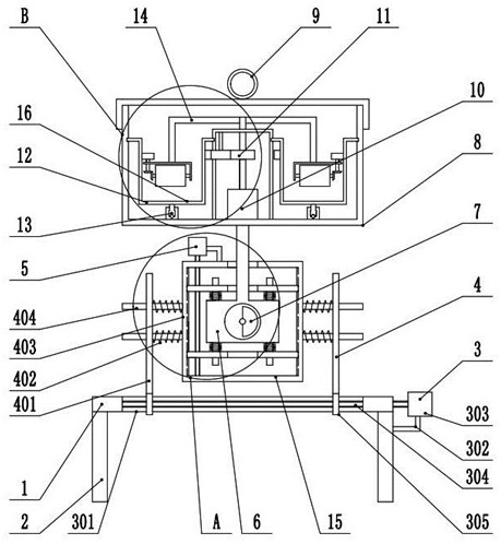
[0033] see Figure 1-7 , a grinding test equipment, including a mounting base 1 and a support leg 2 fixed on the bottom of the mounting base 1;

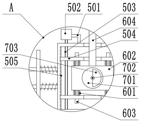
[0034] The mounting base 1 is provided with a vibration assembly 15, and the vibration assembly 15 includes a horizontal adjustment mechanism 3, a horizontal vibration mechanism 4, a vertical adjustment mechanism 5, a vertical vibration mechanism 6 and a vibration mechanism 7, and the horizontal adjustment mechanism 3 is used for Adjust the horizontal vibration mechanism 4, the vertical adjustment mechanism 5 is used to adjust the vertical vibration mechanism 6, and the vibration mechanism 7 is used to drive the horizontal vibration mechanism 4 and the vertical vibration mechanism 6 to vibrate;

[0035] The horizontal adjustment mechanism 3 is arranged on the mounting base 1, the horizontal vibration mechanism 4 is fixed on the horizontal adjustment mechanism 3, the vertical adjustment mechanism 5 is arranged on the horizontal vibrat...

Embodiment 2

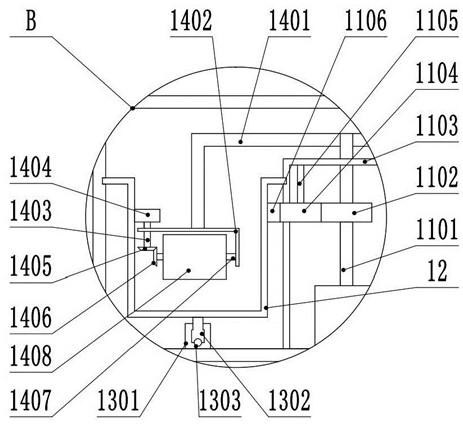
[0048] see image 3 The other content of this embodiment is the same as that of Embodiment 1, except that the rotating mechanism 13 includes a rotating outer tank 1301 fixed at the bottom of the box body 8, and the rotating outer tank 1301 is connected to the rotating ring 1302 in rotation, and the rotating ring 1302 and Several balls 1303 are arranged between the rotating outer grooves 1301, and the rotating ring 1302 is fixedly connected with the grinding ring groove 12. Specifically, when the grinding ring groove 12 rotates, the rotating ring 1302 will rotate around the rotating outer groove 1301.


PUM


Abstract

The invention discloses a grinding test device, which relates to the technical field of physical test equipment, and comprises a mounting base and support legs fixed on the bottom of the mounting base; a vibrating component is arranged on the mounting base, and the vibrating component includes a lateral adjustment mechanism, a lateral The vibration mechanism, the vertical adjustment mechanism, the vertical vibration mechanism and the vibration mechanism; the vertical vibration mechanism is fixedly connected to the box body; the box body is threadedly connected to the cover; the box body is fixedly connected to the first motor; the output shaft of the first motor is fixedly connected to the grinding assembly, The grinding assembly includes a transmission mechanism, a grinding ring groove and a rotation mechanism; the transmission mechanism is fixedly connected to the dial mechanism, and the present invention can adjust the lateral vibration mechanism by setting a horizontal adjustment mechanism, and adjust the lateral amplitude, and can adjust the vibration by setting a vertical adjustment mechanism. The vertical vibration mechanism adjusts the vertical vibration amplitude. Combined with the vibration mechanism, it can drive the horizontal vibration mechanism and the vertical vibration mechanism, which increases the efficiency of the grinding test and enriches the functions of the overall equipment.

Description

technical field [0001] The invention relates to the technical field of physical test equipment, in particular to a grinding test equipment. Background technique [0002] Grinding is the use of abrasive particles coated or pressed on the grinding tool to finish the processing surface (such as cutting) through the relative movement of the grinding tool and the workpiece under a certain pressure. Grinding can be used to process various metal and non-metal materials. The processed surface shapes include plane, inner and outer cylindrical and conical surfaces, convex and concave spherical surfaces, threads, tooth surfaces and other profiles. Vibration grinding is to add vibration to the relative movement between the abrasive and the workpiece during the grinding process, and its main purpose is to improve the processing efficiency. [0003] In the prior art, by driving the annular groove to periodically reciprocate up and down under the action of the combined assembly of the tel...

Claims


Application Information

Patent Timeline
Patent Type & Authority Patents(China)
IPC IPC(8): B24B31/073B24B31/12
CPCB24B31/073B24B31/12
Inventor 臧桂美王培义王泌宝
Owner WEIFANG BUSINESS VOCATIONAL COLLEGE
Why Eureka
Try Eureka