Dynamic electric field fresh-keeping container
A container and dynamic electric field technology, applied in the field of containers, can solve the problems of easy spoilage and long delivery time of food materials, and achieve the effect of ensuring long storage time, improving freshness and long-term storage time
- Summary
- Abstract
- Description
- Claims
- Application Information
AI Technical Summary
Problems solved by technology
Method used
Image

Examples
Embodiment 1
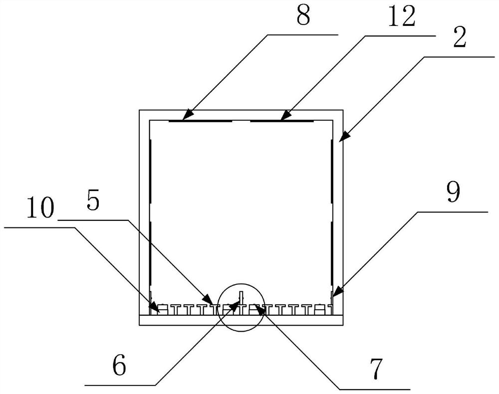
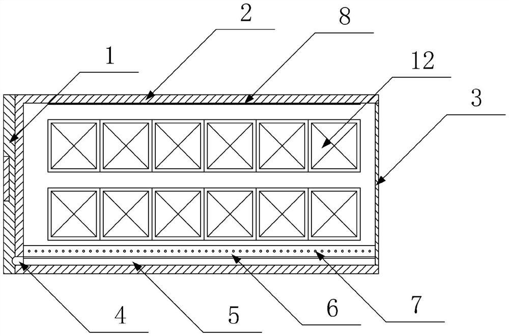
[0036] Such as figure 1 , 2 As shown, a dynamic electric field fresh-keeping container includes a fresh-keeping container main body 2, and a refrigeration device 1 arranged at the rear end of the fresh-keeping container main body 2 is arranged at the bottom end of the rear side wall of the fresh-keeping container main body 2 and runs through the fresh-keeping container main body 2. The cold air outlet 4 connected to the refrigeration equipment 1, several parallel T-shaped air-introducing ribs 5 arranged on the inner bottom side of the fresh-keeping container main body 2, and the box door 3 arranged at the front end of the fresh-keeping container main body 2, the fresh-keeping container main body 2 is also provided with an auxiliary loading structure and a dynamic electric field generating structure.
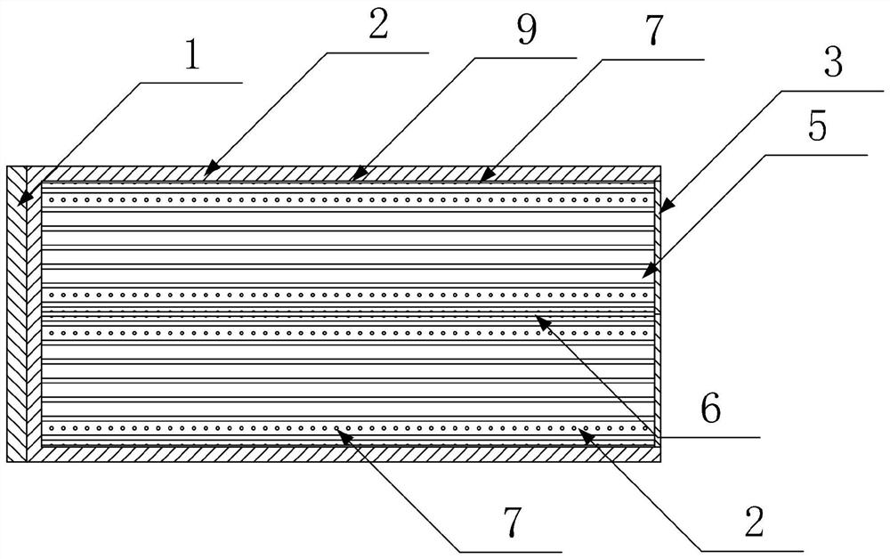
[0037] Such as image 3 As shown, the auxiliary loading structure consists of a center divider 6, a side guide 9, a hydraulic platform 10, several rolling structures 7 that are...
Embodiment 2
[0051] Such as Figure 5 As shown, the difference between this embodiment and Embodiment 1 is that the dynamic electric field generating structure is composed of an insulating layer 11 and a conductive metal plate 12 arranged on the insulating layer 11; the conductive metal plates 12 are arranged in a row, And sequentially electrically connected.
[0052] The specific structure and principle of the dynamic electric field generating structure are the same as the patent application with the application number 2021210673732 and the name is an electric field generating structure. The difference is that the independent insulating bottom plate is replaced with a better insulating layer. According to the above-mentioned patent application combined with the content of this application, technical staff can complete its setting and use without creative work, and will not go into details here.
Embodiment 3
[0054] Such as Figure 6 As shown, the difference between this embodiment and Embodiment 1 is that the dynamic electric field generating structure is composed of an insulating base plate 8 and a cross-formed conductive metal strip 13 arranged on the insulating base plate 8; the insulating base plate 8 is composed of Arranged in rows, the conductive metal strips 13 crossed into a network on the same row of insulating base plates 8 are electrically connected in sequence.
[0055] The specific structure and principle of this dynamic electric field generating structure are the same as the patent application with the application number 202110689757.6 and the name is Lightweight Electric Field Generating Structure Based on Electric Field Generator. Those skilled in the art do not need to pass the inventive step based on the above patent application and the content of this application. It can be set up and used with a little labor, so I won’t go into details here.
PUM
 Abstract
Description
Claims
Application Information