
Push-pull device for equipment in box body

A technology of push-pull devices and equipment, which is applied in the field of push-pull devices, and can solve the problems of complex operation, unusability, and large volume of push-pull equipment

Active Publication Date: 2021-08-13
HUBEI SANJIANG AEROSPACE WANFENG TECH DEV
View PDF5 Cites 0 Cited by
  • Summary
  • Abstract
  • Description
  • Claims
  • Application Information

AI Technical Summary

Problems solved by technology

The filling cart must have a power supply, otherwise it cannot be used
[0003] It can be seen that the above-mentioned loading trolley pushes and pulls the equipment in the box, which has problems such as complicated operation, large volume, and heavy weight, which greatly reduces the push-pull efficiency of the equipment.

Method used


Image

  • Push-pull device for equipment in box body
  • Push-pull device for equipment in box body
  • Push-pull device for equipment in box body

Examples


Embodiment Construction

[0029] In order to make the object, technical solution and advantages of the present invention clearer, the present invention will be further described in detail below in conjunction with the accompanying drawings and embodiments. It should be understood that the specific embodiments described here are only used to explain the present invention, not to limit the present invention. In addition, the technical features involved in the various embodiments of the present invention described below can be combined with each other as long as they do not constitute a conflict with each other.

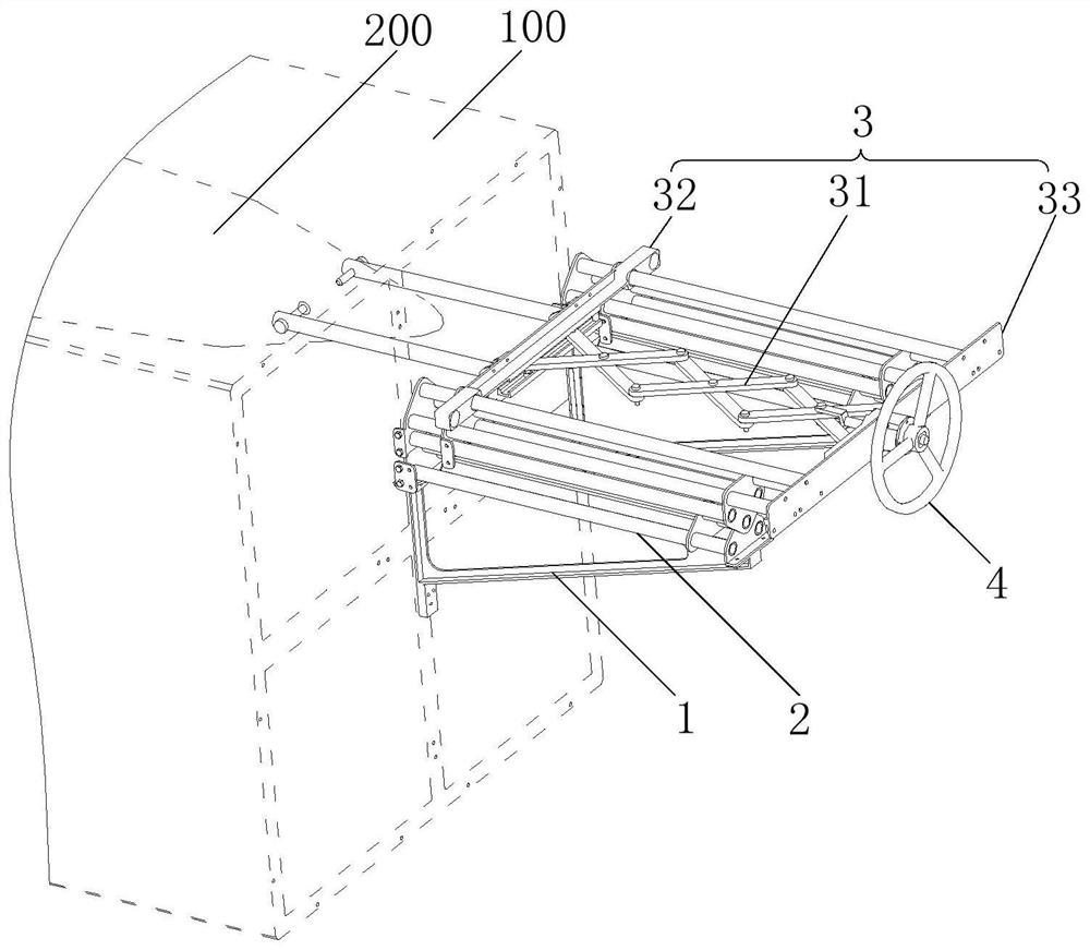
[0030] figure 1 It is a schematic diagram of the use of a push-pull device for equipment in a box provided by the embodiment of the present invention, as shown in figure 1 As shown, the push-pull device includes a support 1 , at least one telescopic rod 2 , a scissor frame assembly 3 and a drive assembly 4 .

[0031] The bracket 1 is used to be fixed on the box body 100, and one end (left end)...


PUM


Abstract

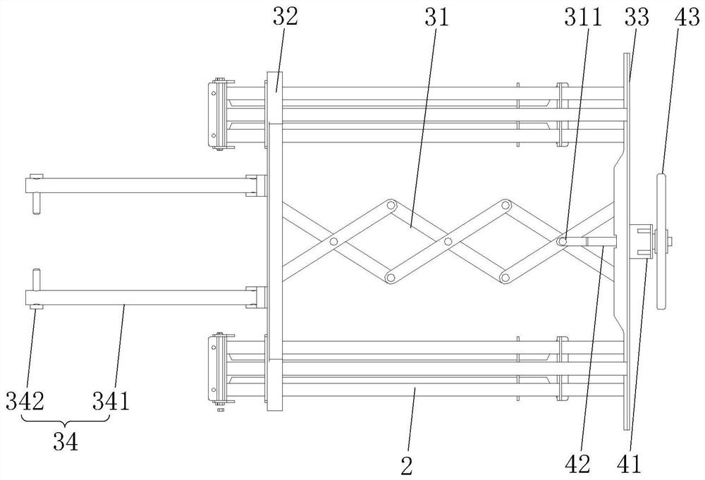
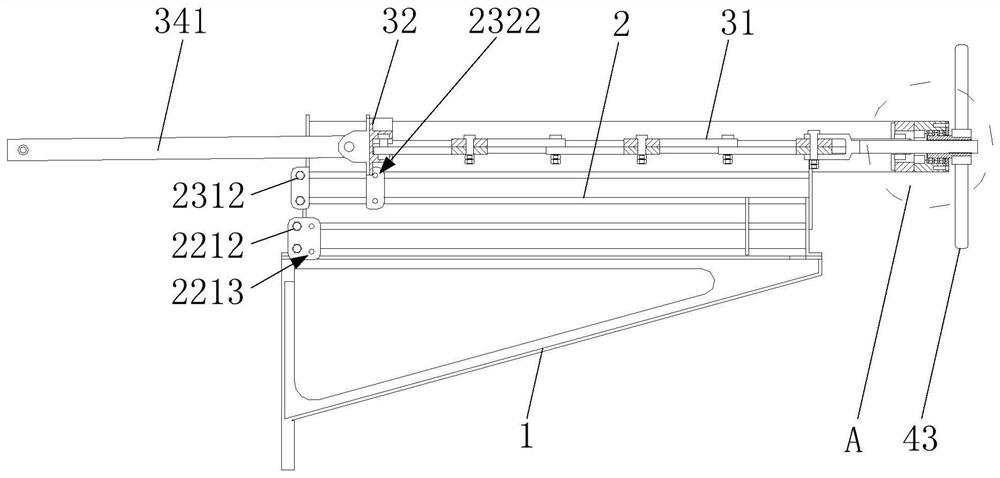
The invention discloses a push-pull device for equipment in a box body, and belongs to the technical field of mechanical transmission. The push-pull device comprises a support, at least one telescopic rod, a shear shank assembly and a driving assembly. The support is fixed to the box body, and one end of the telescopic rod is fixed to the support. The shear shank assembly comprises a shear shank, a first movable plate and a second movable plate, one end of the shear shank is hinged to the first movable plate, the other end of the shear shank is hinged to the second movable plate, the first movable plate is glidingly arranged at one end of the telescopic rod in a sleeving mode, and the second movable plate is fixedly connected with the other end of the telescopic rod. The driving assembly comprises a nut and a screw, the screw is coaxially inserted into the nut, and one end of the screw is fixedly connected with one cross fulcrum of the shear shank. The push-pull device for the equipment in the box body is easy to operate, small in size, light in weight and capable of conveniently pushing and pulling the equipment in the box body.

Description

technical field [0001] The invention belongs to the technical field of mechanical transmission, and more specifically relates to a push-pull device for equipment in a box. Background technique [0002] Currently, loading carts are usually used to push and pull equipment into and out of long and narrow boxes. The filling trolley is driven by a motor, which can push the entire equipment into the box and pull it out of the box. The loading cart has comprehensive pushing and pulling functions, high reliability and relatively mature technical application. However, when using a loading cart, it needs to be aligned so that it aligns with the equipment gripper holes. Adjustment will take a lot of time, and sometimes there is no loading trolley at the inspection site, and it must be transported from other places, especially in outdoor occasions, the loading trolley needs to be carried with the vehicle. Due to the various and complicated mechanisms for loading carts, large volume, ...

Claims


Application Information

Patent Timeline
Patent Type & Authority Applications(China)
IPC IPC(8): B65G65/00B65G65/32B65G65/40
CPCB65G65/32B65G65/40B65G65/00B65G2201/02
Inventor 李海俊郑云云何云峰李德胜彭俊赵长洋王代宏
Owner HUBEI SANJIANG AEROSPACE WANFENG TECH DEV
Learn More