Existing building anti-floating system based on embedded self-propelled anchor rods and construction method thereof

A technology of existing buildings and construction methods, applied in construction, infrastructure engineering, infrastructure repair and other directions, can solve problems such as cracking and seepage, easy to float, damage to supporting structures, etc., to increase the contact area and increase the viscosity. The effect of knotting ability and ensuring stability

Active Publication Date: 2021-08-13
四川康久美建筑工程有限公司
View PDF5 Cites 4 Cited by
  • Summary
  • Abstract
  • Description
  • Claims
  • Application Information

AI Technical Summary

Problems solved by technology

[0002] When the self-weight of the building and the soil covering the bottom cannot offset the buoyancy generated by the groundwater, the bottom of the existing building is likely to float up due to the action of water pressure, which will cause the supporting structure of the building to be deformed under compression. In severe cases, the supporting structure will be destroyed, affecting the stability of the building; Moreover, since the post-pouring belt, construction joints or cracks formed in the later stage of the raft are weak links, the bottom of the raft is subjected to water pressure for a long time, and the post-pouring belt, construction joints or cracks of the raft further develop, resulting in the raft of the basement of the existing building. Or cracking and water seepage, there is a safety hazard
Moreover, most of the existing anti-floating control methods use the method of drilling pressure relief to release the water pressure of the anti-floating floor of the building, and then apply anchor rods for anti-floating treatment. The distribution of anchor rods is unreasonable. When the subsequent groundwater level rises, Especially in extreme weather such as heavy rain and other environments, the water pressure will always have a pressure effect on the floating floor, and the problem of cracking and leakage of the floating floor has not been solved.

Method used


Image

  • Existing building anti-floating system based on embedded self-propelled anchor rods and construction method thereof
  • Existing building anti-floating system based on embedded self-propelled anchor rods and construction method thereof
  • Existing building anti-floating system based on embedded self-propelled anchor rods and construction method thereof

Examples


Embodiment

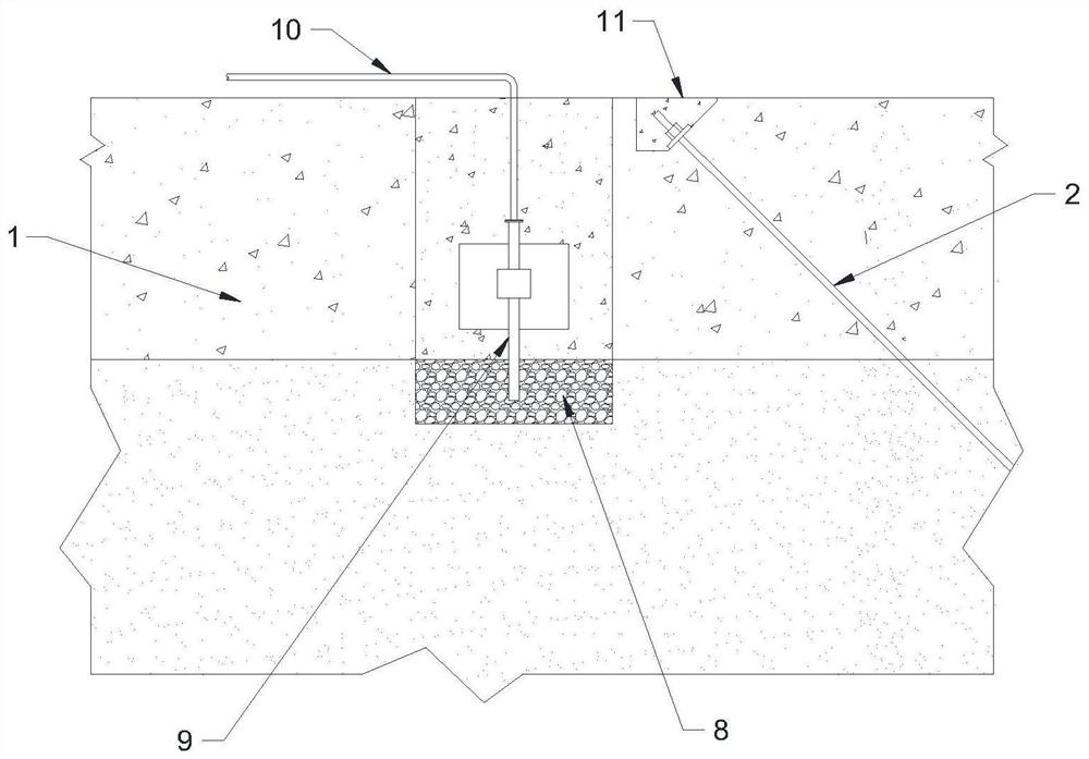
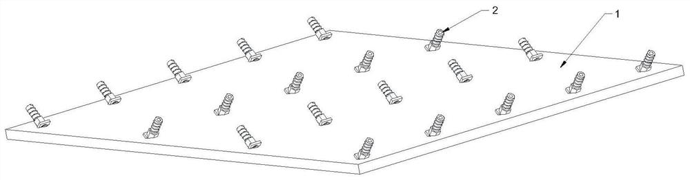
[0036] See Figure 1-6 However, the existing building floating system based on the embedded self-joined anchor includes an anchor group that is applied to the existing building anti-floating bottom plate 1, and the anchor population includes a plurality of self-propelled floating anchor rods 2, each self The angle between the in-plane anti-floating anchor 2 and the plane of the anti-floating bottom plate 1 is 40-75 degrees; the auto-circulating anchor rod 2 in the anchor group is arranged in a matrix, and each row is self-entered. The floating anchor 2 is disposed in parallel, each column is adjacent to two auto-floating anchor rods, and also includes a pressure relief tube 9 inserted on the anti-floating bottom plate 1, and the bottom end end of the pressure relief tube 9 is located Floating bottom plate 1, the other end is connected to the building outlet pool or municipal rain sewage pipe network.

[0037] In the present embodiment, the construction method of the existing buildi...


PUM


Abstract

The invention relates to the technical field of existing building anti-floating, and discloses an existing building anti-floating system based on embedded self-propelled anchor rods and a construction method thereof. The existing building anti-floating system comprises an anchor rod group applied to an existing building anti-floating bottom plate, the anchor rod group comprises a plurality of self-propelled anti-floating anchor rods applied at 40-75 degrees, the self-propelled anti-floating anchor rods in the anchor rod group are oppositely arranged in a matrix mode, design requirements can be greatly met, horizontal disturbance can be resisted, and the displacement of the building in the horizontal direction is reduced; meanwhile, an anti-floating treatment mode of combining the self-propelled anti-floating anchor rods and a pressure relief device is adopted, so that the anti-floating plate can be effectively reinforced, the damaged part of the anti-floating plate can be effectively recovered, and cavities and gaps below the anti-floating plate can be effectively filled; and when the distribution density of the self-propelled anti-floating anchor rods is designed, the pressure relief effect of the pressure relief device is fully considered, so that the use amount of the self-propelled anti-floating anchor rods can be reduced while the floating problem of the existing building is effectively solved.

Description

Technical field [0001] The present invention relates to the field of existing buildings, which relates to existing building float systems and construction methods based on embedded self-conducting anchors. Background technique [0002] When the buildings from the buildings and the bottom soil cannot counteract the floating force generated by the groundwater, the bottom of the building is prone to the water pressure, which causes the building support structure to be modified, and the support structure is destroyed, affecting the stability of the building; Moreover, because the cracks of the rafting, the cracks formed in the post-construction seam is weak, the bottom of the raft is long-term water pressure, the rear ladle, the construction seam, the construction seam or cracks, resulting in both construction basement raft Or cracking water, there is a safety hazard. Moreover, the existing anti-float treatment method is mostly leaked into the water pressure of the building anti-floa...

Claims


Application Information

Patent Timeline
Patent Type & Authority Applications(China)
IPC IPC(8): E02D31/12E02D5/74E02D37/00E02D15/02
CPCE02D31/12E02D5/74E02D37/00E02D15/02E02D2250/003E02D2600/30
Inventor 斯树友何建祥
Owner 四川康久美建筑工程有限公司
Why Eureka
Try Eureka