Vertical wind tunnel model pitching-rolling test device and use method

A test device and wind tunnel test technology, which is used in measurement devices, aerodynamic tests, aircraft component testing, etc., can solve the problem of wingtip vortex development interference, large damage to the aerodynamic shape of flying-wing aircraft, and poor adaptability to different models of support devices. and other problems, to achieve the effect of high rotation accuracy, high simulation accuracy and convenient installation.

Active Publication Date: 2021-08-13
LOW SPEED AERODYNAMIC INST OF CHINESE AERODYNAMIC RES & DEV CENT
View PDF18 Cites 7 Cited by
  • Summary
  • Abstract
  • Description
  • Claims
  • Application Information

AI Technical Summary

Problems solved by technology

[0004] In the prior art, the wind tunnel test system for researching aircraft pitching characteristics is mainly established in traditional horizontal wind tunnels for conventional layout aircraft. Although it can meet the routine tests such as dynamic derivative test and high angle of attack unsteady test, it still faces some problems. Problems: 1) There are inherent defects in the traditional horizontal wind tunnel for rotary flight tests. Since the gravity direction of the model is perpendicular to the axis of the wind tunnel test section, it is difficult to solve the balance problem in the model rotation and the weight of the rotary part; 2 ) The free pitch / roll wind tunnel test technology is still a blank in domestic research. Since the flying wing aircraft is prone to enter a dangerous out-of-control roll state during flight, it is necessary to conduct in-depth research on the mechanism and improvement measures of this phenomenon in the wind tunnel, resulting in The demand for testing the free pitch / roll characteristics of flying-wing aircraft has increased sharply, and the existing wind tunnel test system can no longer meet the test requirements of unconventional aircraft such as flying-wing aircraft; 3) The existing free pitch / roll The device usually adopts the wingtip support method that penetrates the fuselage. This support method not only greatly damages the aerodynamic shape of the flying-wing aircraft, but also seriously affects the accuracy and reliability of the test results, and even results in completely opposite tests. Results; 4) The wingtip support method makes it very difficult to adjust the position of the center of rotation of the model, and the installation of the vertical plate at the wingtip also seriously interferes with the development of the wingtip vortex, which affects the accuracy of the test results. Poor adaptability

Method used


Image

  • Vertical wind tunnel model pitching-rolling test device and use method
  • Vertical wind tunnel model pitching-rolling test device and use method
  • Vertical wind tunnel model pitching-rolling test device and use method

Examples


Embodiment 1

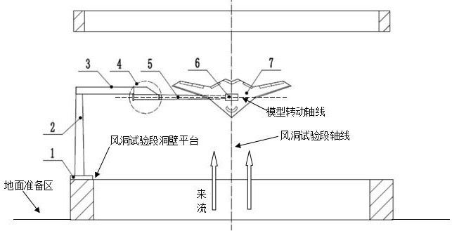
[0050] Embodiment 1 of the present invention provides a vertical wind tunnel model pitch-roll test device, wherein the test device includes:

[0051] A base 1, the base 1 is fixedly installed on the wall platform of the vertical wind tunnel test section;

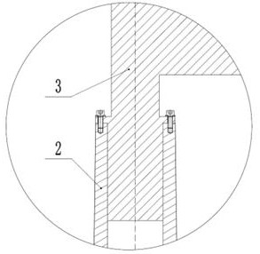
[0052] A column 2, the bottom end of the column 2 is fixedly connected to the base 1;

[0053] A support rod 3, the support rod 3 is located between the upright column 2 and the abdominal support bending rod 5, one end of the support rod 3 is fixedly connected to the top of the upright column 2, and the other end is connected to the abdominal support through the rotating assembly 4 One end of the curved rod 5 is connected, and the axis of the support rod 3 is parallel to the diameter direction of the wind tunnel test section;

[0054] The rotating assembly 4 is installed on the end of the support rod 3 away from the column 2;

[0055] The belly brace bending rod 5 is fixedly connected to the mounting base 6 at the end far ...

Embodiment 2

[0086]Embodiment 2 of the present invention also provides a method for using a vertical wind tunnel model pitch-roll test device, such as Figure 10 As shown, the usage steps are as follows:

[0087] Step S10: Install the base 1 on the wall platform of the vertical wind tunnel test section, and adjust the direction and level of the base 1;

[0088] Step S20: installing the column 2 on the base 1, and adjusting the direction and verticality of the base 1;

[0089] Step S30: Insert the rotating part 32 of the support rod 3 into the top of the column 2, add lubricating grease between the contact surface of the rotating part 32 and the column 2 to reduce friction, and rotate the support rod 3 above the ground so that The support rod 3 is located outside the wind tunnel test;

[0090] Step S40: install the rotating assembly 4 on the front end of the supporting part 31; place the electromagnetic brake 41, the magnetic grid assembly 42, the deep groove ball bearing 43, and the stru...


PUM


Abstract

The invention is suitable for the technical field of wind tunnel tests, and provides a vertical wind tunnel model pitching-rolling test device and a use method, and the test device comprises a base which is fixedly installed on a vertical wind tunnel test section tunnel wall platform; a stand column, the bottom end of the stand column being fixedly connected with the base; a supporting rod, located between the stand column and the web supporting bent rod, one end of the supporting rod being fixedly connected with the top end of the stand column, the other end of the supporting rod being connected with one end of the web supporting bent rod through a rotating assembly, and the rotating assembly being installed at the end, away from the stand column, of the supporting rod; and a belly supporting bend rod, the end, away from the rotating assembly, of the belly supporting bent rod being fixedly connected with the installation base, and the installation base being fixedly installed on the belly of the aircraft model. Free pitching / rolling motion of the airplane model under the action of aerodynamic force can be achieved, the structure is simple, mechanism rotation damping is small, interference is small, precision is high, and installation is easy, convenient and reliable.

Description

technical field [0001] The invention relates to the field of aircraft wind tunnel tests, in particular to a vertical wind tunnel model pitch-roll test device and a method of use. Background technique [0002] Aircraft pitch characteristics are important indicators for evaluating aircraft maneuverability and aerodynamic performance. The research on aircraft pitch characteristics through wind tunnel tests has the advantages of low cost, low risk, and high precision. [0003] Aircraft pitching test devices are classified according to the constraints, mainly including pitching forced oscillation test devices and free pitching test devices. There are mainly four types of model support methods, which are: belly support, tail support, wingtip support and back support. In the wind tunnel test, the support device supports or drives the pitching motion of the aircraft model, and is used for unsteady tests at large angles of attack and dynamic derivative tests. [0004] In the prior ...

Claims


Application Information

Patent Timeline
Patent Type & Authority Applications(China)
IPC IPC(8): G01M9/02G01M9/04G01M9/08B64F5/60
CPCB64F5/60G01M9/02G01M9/04G01M9/08
Inventor 范镓驿张海酉孙海生杨洪森孔鹏朱任宇颜来
Owner LOW SPEED AERODYNAMIC INST OF CHINESE AERODYNAMIC RES & DEV CENT
Why Eureka
Try Eureka