Testing method and testing device for near-to-eye display equipment and storage medium
A near-eye display and testing method technology, which is applied in the direction of testing optical properties, etc., can solve the problems of inaccurate measurement results and prolonged measurement time, and achieve the effects of accurate measurement values, reduced brightness deviation, and improved test efficiency
- Summary
- Abstract
- Description
- Claims
- Application Information
AI Technical Summary
Problems solved by technology
Method used
Image
Examples
Embodiment 1
[0060] The test method of the field of view test in the prior art is to simulate eyeball rotation through the imaging device, that is, to move the position and angle of the imaging lens, and capture images multiple times to simulate the imaging of the eyeball. Due to the need to obtain measurement pictures multiple times, in practical applications, the field of view testing device based on the above testing method is costly, complicated to operate, and time-consuming.
[0061] Therefore, the present invention provides a method for testing the field of view of a near-eye display device. The test method realizes rapid detection of the field of view of a near-eye display device by acquiring a complete test picture at one time, greatly shortens the measurement time, and improves test efficiency.
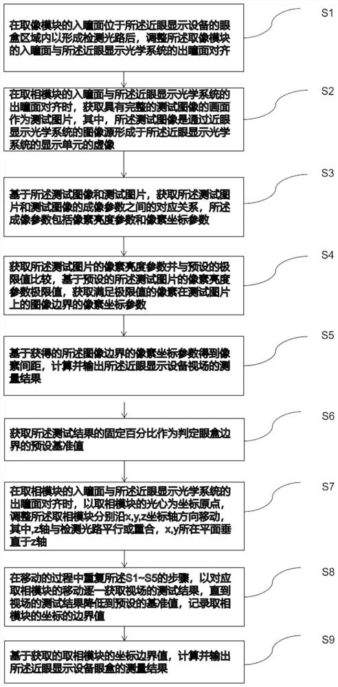
[0062] A method for testing the field of view of a near-eye display device provided by the present invention, specifically, refer to figure 1 , including the following steps:
[0063] S...
Embodiment 2
[0085] In order to more intuitively describe the test points of the above-mentioned test method for the field of view of a near-eye display device, this embodiment combines figure 2 A schematic diagram of an imaging and field of view testing system is shown, specifically:
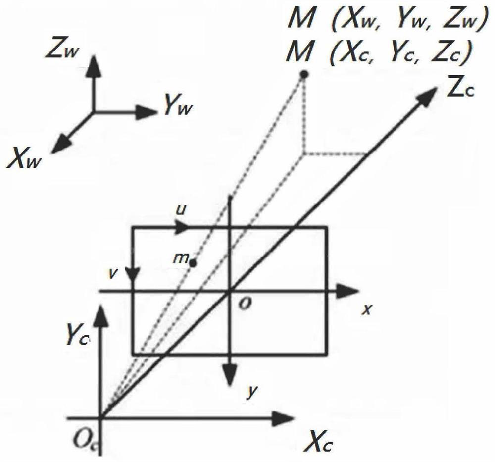
[0086] combine figure 2 with image 3 ,first, figure 2 Shown is a schematic diagram of the imaging and field of view testing system of an embodiment, including the NED display screen 2 of the near-eye display device under test, the NED optical lens 3 of the near-eye display device under test, the detection lens 6 and the detection camera 7. In the phase acquisition module, the entrance pupil field of view of the detection lens must at least cover the field of view of the near-eye display device under test, and the entrance pupil of the phase acquisition module is set at the entrance pupil of the detection lens.
[0087] In this example, after the NED display screen 2 passes through the NED optical len...
Embodiment 3
[0120] In order to better implement the method for testing the field of view of a near-eye display device provided in Embodiment 1 or 2 above, this embodiment further provides a test device 10 for detecting the field of view of a near-eye display device, such as Figure 5 As shown, it includes: a positioning module 11 , an imaging module 12 , a verification and calibration module 13 , an image processing module 14 and a main control module 15 .
[0121] The positioning module 11 is configured to adjust the position of the near-eye display device to form a detection optical path and adjust the alignment of the entrance pupil plane of the phase acquisition unit with the exit pupil plane of the near-eye display optical system.
[0122] It should be noted that in order to align the entrance pupil plane of the phase capture module with the exit pupil plane of the near-eye display optical device, the positioning module 11 needs to be adjusted in position and angle, wherein the positi...
PUM
 Abstract
Description
Claims
Application Information
 - R&D
- Intellectual Property
- Life Sciences
- Materials
- Tech Scout
- Unparalleled Data Quality
- Higher Quality Content
- 60% Fewer Hallucinations
Browse by: Latest US Patents, China's latest patents, Technical Efficacy Thesaurus, Application Domain, Technology Topic, Popular Technical Reports.
© 2025 PatSnap. All rights reserved.Legal|Privacy policy|Modern Slavery Act Transparency Statement|Sitemap|About US| Contact US: help@patsnap.com


