
Device for measuring refractive index of gas based on light path folding and vacuumizing mode

A gas refractive index and vacuuming technology, which is used in measurement devices, phase influence characteristics measurement, material analysis by optical means, etc., can solve the problems of unstable pressure change process, large gas temperature change, and small number of interference fringes, etc. Achieve stable and slow changes, compress the space occupied, and the changes in air pressure are stable and uniform.

Pending Publication Date: 2021-08-13
JIANGXI NORMAL UNIV
View PDF13 Cites 0 Cited by
  • Summary
  • Abstract
  • Description
  • Claims
  • Application Information

AI Technical Summary

Problems solved by technology

[0002] Michelson interferometer is widely used in the field of precision measurement. Measuring the refractive index of gas is one of the important applications of Michelson interferometer, and it is also an important experimental project in the physics experiment course of colleges and universities. Inflating and pressurizing the method, because the special gas chamber is small, the pressure change process is not stable enough, the gas temperature changes greatly, and the optical path is too short, resulting in a small number of interference fringes, and the measurement effect is not large, so large errors will occur; This method can only measure the refractive index of air, and the refractive index of gases with other properties cannot be measured by traditional Michelson interferometry

Method used


Image

  • Device for measuring refractive index of gas based on light path folding and vacuumizing mode
  • Device for measuring refractive index of gas based on light path folding and vacuumizing mode
  • Device for measuring refractive index of gas based on light path folding and vacuumizing mode

Examples


Embodiment Construction

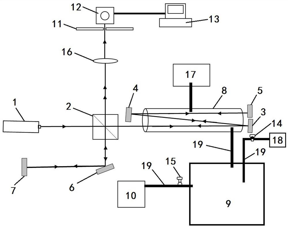
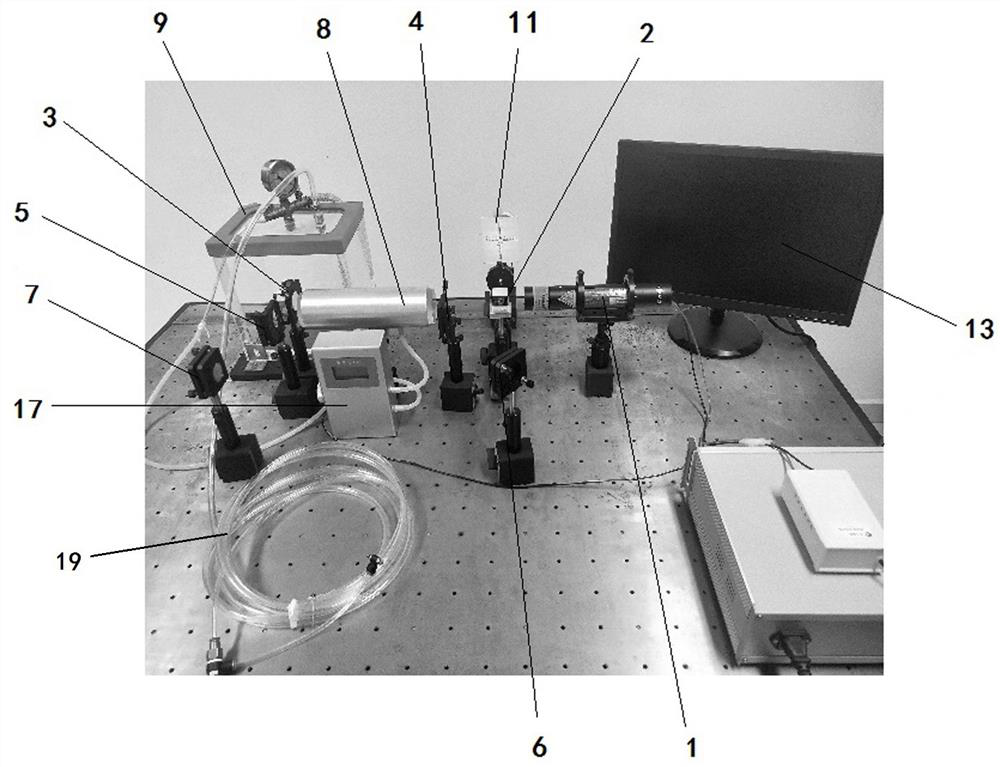
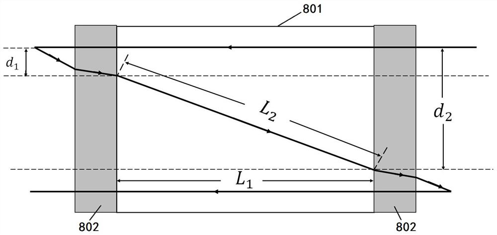
[0031] In order to understand the above-mentioned purpose, features and advantages of the present invention more clearly, the present invention will be further described in detail below in conjunction with the accompanying drawings and specific embodiments. In the following description, many specific details are set forth in order to fully understand the present invention, but the present invention can also be implemented in other ways different from those described here, therefore, the present invention is not limited to the specific embodiments disclosed below limit.

[0032] Unless otherwise defined, the technical terms or scientific terms used herein shall have the common meanings understood by those having ordinary skill in the field to which this application relates. "First", "second" and similar words used in the specification and claims of this patent application do not indicate any sequence, quantity or importance, but are only used to distinguish different components...


PUM

PropertyMeasurementUnit
Outer diameteraaaaaaaaaa
Thicknessaaaaaaaaaa
Lengthaaaaaaaaaa

Abstract

The invention relates to a device for measuring the refractive index of gas based on a light path folding and vacuumizing mode. The device comprises a self-built light path folding type Michelson interferometer, a special gas chamber, a vacuum pumping module and a data acquisition system; the light path folding type Michelson interferometer comprises a light source, a square beam splitter prism, five plane reflectors and a beam expander; the special gas chamber is an aluminum circular tube with quartz glass observation windows at the two ends; the vacuum pumping module comprises a vacuum hose, a vacuum buffer chamber, a sucking pump and a digital temperature barometer; the data acquisition system comprises an optical screen, a light intensity detector and a computer. According to the invention, five plane reflectors are used to realize light path folding, so that the effect to be measured is greatly enhanced and the space required by the instrument device is compressed; the refractive indexes of various gases can be measured by adopting a measurement mode of firstly vacuumizing and then filling the gases, and the change of the air pressure in the gas chamber can be uniform and slow by arranging the vacuum buffer chamber, so that the accuracy of measuring the refractive indexes of the gases is improved.

Description

technical field [0001] The application relates to the field of precision measurement technology of gas refractive index and teaching instruments and equipment, in particular to a device for measuring gas refractive index based on optical path folding and vacuuming. Background technique [0002] Michelson interferometer is widely used in the field of precision measurement. Measuring the refractive index of gas is one of the important applications of Michelson interferometer, and it is also an important experimental project in the physics experiment course of colleges and universities. Inflating and pressurizing the method, because the special gas chamber is small, the pressure change process is not stable enough, the gas temperature changes greatly, and the optical path is too short, resulting in a small number of interference fringes, and the measurement effect is not large, so large errors will occur; This method can only measure the refractive index of air, and the traditi...

Claims


Application Information

Patent Timeline
IPC IPC(8): G01N21/45G01N21/01
CPCG01N21/45G01N21/01G01N2021/458G01N2021/0112
Inventor 官盛果孙静乐建新程晏蓓徐小凤黄晓霞董元皓
Owner JIANGXI NORMAL UNIV
Features
  • Generate Ideas
  • Intellectual Property
  • Life Sciences
  • Materials
  • Tech Scout
  • Unparalleled Data Quality
  • Higher Quality Content
  • 60% Fewer Hallucinations
Learn More