A flexible and sensitive pressure sensing device based on porous structure

A pressure-sensitive, porous structure technology, applied in the field of sensing devices, can solve problems such as low pressure sensitivity, achieve high sensitivity, enhance the change of electrical quantity, and increase the effect of deformation quantity

Active Publication Date: 2020-11-06
ZHEJIANG UNIV
View PDF14 Cites 0 Cited by
  • Summary
  • Abstract
  • Description
  • Claims
  • Application Information

AI Technical Summary

Problems solved by technology

[0006] In order to solve the problem of low pressure sensitivity of traditional flexible pressure sensors, to meet the requirements of critical installation positions for sensing accuracy

Method used


Image

  • A flexible and sensitive pressure sensing device based on porous structure
  • A flexible and sensitive pressure sensing device based on porous structure
  • A flexible and sensitive pressure sensing device based on porous structure

Examples


Embodiment 1

[0052] The test conditions for this 0.1N~1N reciprocating cyclic force loading test are: the tensile and compressive testing machine conducts a tensile and compressive test on the flexible porous pressure sensing unit 1 at a speed of 100mm / min, and the minimum pressure applied to the sensing unit by the test is 0.1N, the maximum pressure is 1N. The measured resistance is the resistance of the bottom structure of the flexible porous sensitive pressure sensing unit 1 .

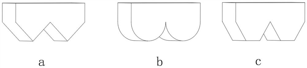
[0053] For the reciprocating cyclic force loading experiment of 0.1N~1N, a triangular sawtooth shape such as image 3 The flexible porous pressure sensing unit 1 shown in a. The sensory detection results of this test are as follows: Figure 4 Shown: the resistance change ratio (the ratio of the maximum value of the resistance change to the lowest resistance during the experiment) is 7 times, the result is as follows Figure 5 as shown; using a double semicircle shape such as image 3 The flexible porous pres...

Embodiment 2

[0057] Since the bottom shape structures of the flexible porous pressure sensing unit 1 with different shapes have different sensitivity characteristics, different bottom shape structures can be used in different application scenarios.

[0058] For the sensing unit on the surface of a mechanical dexterous hand, a triangular sawtooth shape such as image 3 The flexible porous pressure sensing unit 1 shown in a. It is relatively excellent in sensitivity, and is suitable for use in precise operation machines such as mechanical dexterous hands.

[0059] For the sensor array on the surface of the human-computer interaction robot, the trapezoidal shape can be used, such as image 3 The flexible porous pressure sensing unit 1 shown in c. It is relatively insensitive to external force changes, preventing false alarms caused by oversensitive sensors during human-computer interaction. At the same time, due to the influence of shape factors, units with different bottom shapes have dif...


PUM


Abstract

The invention discloses a porous structure-based flexible sensitive pressure sensing device. The device is formed by a flexible porous sensitive pressure sensing unit, a flexible porous casing, a flexible electrode layer, a flexible substrate and a flexible porous substrate through tight assembly from top to bottom in sequence; a groove is formed in the bottom surface of the flexible porous casing; the flexible porous substrate is embedded in the groove through interference fit; the flexible electrode layer is connected with an external analysis circuit; a mounting hole is formed in the flexible porous casing right above the flexible porous electrode layer; the flexible porous sensitive pressure sensing unit is mounted in the mounting hole in the flexible porous casing through an interference fit manner; and the bottom surface of the flexible porous sensitive pressure sensing unit is a concave-convex structure designed for the geometric shapes of mounting plans; and the bottom surfaceof the flexible porous substrate is attached to an external mounting plane. The device has the advantages that the device has the physical properties such as small Young's modulus and large coefficient of friction of the porous structure, and the concave-convex structure at the bottom of the unit makes the porous structure more sensitive when sensing external forces.

Description

technical field [0001] The invention relates to a sensing device, in particular to a flexible and sensitive pressure sensing device based on a porous structure. Background technique [0002] At present, as an important part of service robots, mechanical grippers are gradually entering people's daily production and life, and have an increasingly important impact on the development of human society. [0003] In the process of performing precise tasks on service robots, the gripper is the most important execution component. During the working process of the manipulator, the pressure feedback and flexible protection between the fingertips are the basis of the manipulator's action decision-making and object protection. That is to say, the pressure feedback from the fingertips brings a "tactile sense" to the robotic gripper, making it change from a simple actuator to an artificial hand with sensory functions. It is beneficial to realize the function of robot interacting with the...

Claims


Application Information

Patent Timeline
Patent Type & Authority Patents(China)
IPC IPC(8): G01L1/18
CPCG01L1/18
Inventor 杨赓庞高阳衡文正杨华勇
Owner ZHEJIANG UNIV
Why Eureka
Try Eureka