Coated diaphragm with high liquid storage rate as well as preparation method and application thereof

A technology with high liquid storage rate and liquid storage rate, applied in electrical components, electrochemical generators, circuits, etc., can solve the problems of reducing battery electrical performance and increasing battery internal resistance, so as to improve electrical performance and increase liquid storage rate Effect

Inactive Publication Date: 2021-08-13
JIANGSU HORIZON NEW ENERGY TECH CO LTD
View PDF0 Cites 3 Cited by
  • Summary
  • Abstract
  • Description
  • Claims
  • Application Information

AI Technical Summary

Problems solved by technology

[0003] The main components of the binder coating used in the industry include one or more of PVDF, SBR, polyacrylonitrile and other binders, and there are many kinds of coating shapes, such as full coverage coating, dot coating, etc. However, most of them focus on the adhesion between the separator and the pole piece, ignoring the influence of the increase of the binder coating on the battery liquid storage rate, and the lower electrolyte will increase the internal resistance of the battery, thereby greatly reducing the electrical performance of the battery

Method used


Image

  • Coated diaphragm with high liquid storage rate as well as preparation method and application thereof
  • Coated diaphragm with high liquid storage rate as well as preparation method and application thereof
  • Coated diaphragm with high liquid storage rate as well as preparation method and application thereof

Examples


Embodiment 1

[0051] 1. Prepare coating solution;

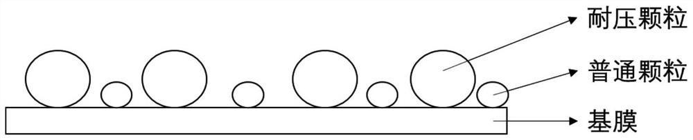
[0052] Select 15g of polyvinylidene fluoride particles with a particle size of 3 μm as pressure-resistant particles, and uniformly disperse them in 85g of ultrapure water to obtain a coating solution;

[0053] 2. Preparation of coated separator

[0054] The coating solution was coated on the surface of a 9 μm polyethylene-based film by micro-gravure roll coating, and dried at 65 degrees Celsius to obtain a coated separator, marked as S1.

[0055] Among them, the coverage of the coating is 100%, the coating thickness is 1.5μm, and the surface density is 1.0g / m 2 .

Embodiment 2

[0057] 1. Prepare coating solution;

[0058] Select 15g of polyvinylidene fluoride particles with a particle size of 3 μm as pressure-resistant particles, and uniformly disperse them in 85g of ultrapure water to obtain a coating solution;

[0059] 2. Preparation of coated separator

[0060] The coating solution was coated on the surface of a 9 μm polyethylene-based film by micro-gravure roll coating, and dried at 65 degrees Celsius to obtain a coated separator, marked as S2.

[0061] Among them, the coverage of the coating is 15%, the coating thickness is 1.5μm, and the surface density is 1.0g / m 2 .

Embodiment 3

[0063] 1. Prepare coating solution;

[0064] Select 3g of PVDF particles with a particle size of 3μm as pressure-resistant particles, and 12g of alumina as ordinary particles with a particle size of 0.8μm, and uniformly disperse them in 85g of ultrapure water to obtain a coating solution; Among them, pressure-resistant particles: ordinary particles The mass ratio of = 1:4;

[0065] 2. Preparation of coated separator

[0066] The coating solution was coated on the surface of a 9 μm polyethylene-based film by micro-gravure roll coating, and dried at 65 degrees Celsius to obtain a coated separator, marked as S3.

[0067] Among them, the coverage of the coating is 100%, the coating thickness is 1.5μm, and the surface density is 1.0g / m 2 .


PUM

PropertyMeasurementUnit
particle diameteraaaaaaaaaa
thicknessaaaaaaaaaa
thicknessaaaaaaaaaa

Abstract

The invention provides a coated diaphragm with a high liquid storage rate, which comprises a base membrane and a coating compounded on the surface of the base membrane. The coating is prepared from a binder containing pressure-resistant particles, and the pressure-resistant particles comprise one or more of a polyacrylate binder, PVDF, SBR, aramid fibers, polyacrylonitrile and polyacrylic acid. The particle size of the pressure-resistant particles is 0.2-10 [mu] m. The compression ratio of the coating ranges from 0.4 to 0.99. According to the invention, a relatively high coating compression ratio is obtained through a special coating design, and the liquid storage rate of the diaphragm is greatly improved while the adhesive force of the diaphragm and a pole piece is maintained, so that the electrical performance of a battery is improved.

Description

technical field [0001] The invention belongs to the technical field of new energy, and in particular relates to a high liquid storage rate coated diaphragm, its preparation method and application. Background technique [0002] The new energy industry is developing rapidly. As an important carrier of new energy, lithium batteries are widely used, and their performance and safety have attracted more and more attention. During the charging and discharging process of lithium batteries, the volume will periodically expand and shrink with charging and discharging, and gaps are likely to be formed between the pole pieces and the diaphragm. These gaps have a high risk of lithium analysis and reduce the cycle life of the battery. Therefore, the industry Neiduo uses a binder coating on the surface of the separator to increase the adhesion between the separator and the pole piece and reduce the negative impact of volume changes on battery performance. [0003] The main components of t...

Claims


Application Information

Patent Timeline
Patent Type & Authority Applications(China)
IPC IPC(8): H01M50/417H01M50/46H01M50/449H01M10/0525
CPCH01M10/0525Y02E60/10
Inventor 张立斌翁星星陈朝晖
Owner JIANGSU HORIZON NEW ENERGY TECH CO LTD
Why Eureka
Try Eureka