
Magnetoelectric dipole antenna structure and antenna array

A technology of dipole antenna and antenna structure, applied in antenna array, antenna grounding switch structure connection, antenna and other directions, can solve the problems of difficult to achieve multi-polarization, difficult antenna processing and molding, poor mechanical strength, etc. Mechanical strength, reducing the difficulty of antenna multi-polarization and antenna processing, and simplifying the effect of feeding network

Active Publication Date: 2021-08-13
CHENGDU T-RAY TECH CO LTD
View PDF8 Cites 3 Cited by
  • Summary
  • Abstract
  • Description
  • Claims
  • Application Information

AI Technical Summary

Problems solved by technology

For the magnetoelectric dipole antenna, the conventional magnetoelectric dipole antenna still has the problem that it is difficult to achieve multi-polarization, and the overall use of a three-dimensional structure with a large cross-section height to realize its function, the processing and forming of the antenna is difficult, and the mechanical strength Poor, difficult to process and integrate into an antenna array structure with low profile requirements

Method used


Image

  • Magnetoelectric dipole antenna structure and antenna array
  • Magnetoelectric dipole antenna structure and antenna array
  • Magnetoelectric dipole antenna structure and antenna array

Examples


Embodiment Construction

[0038] In order to make the purposes, technical solutions and advantages of the embodiments of the present application clearer, the technical solutions in the embodiments of the present application will be clearly and completely described below in conjunction with the drawings in the embodiments of the present application. Obviously, the described embodiments It is a part of the embodiments of this application, not all of them. The components of the embodiments of the application generally described and illustrated in the figures herein may be arranged and designed in a variety of different configurations.

[0039] Accordingly, the following detailed description of the embodiments of the application provided in the accompanying drawings is not intended to limit the scope of the claimed application, but merely represents selected embodiments of the application. Based on the embodiments in this application, all other embodiments obtained by persons of ordinary skill in the art w...


PUM


Abstract

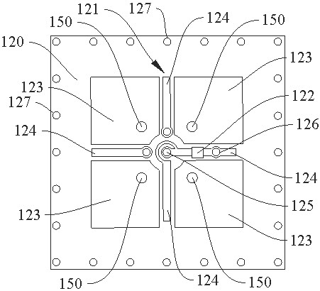
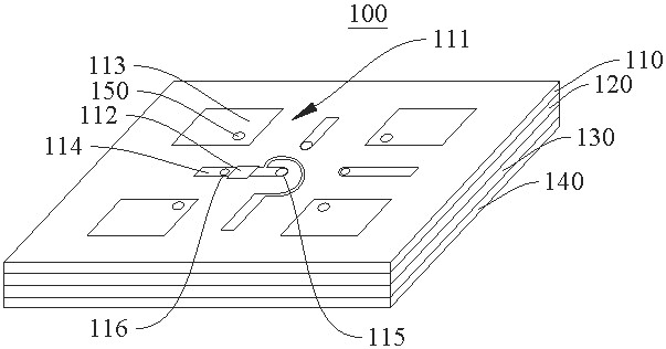
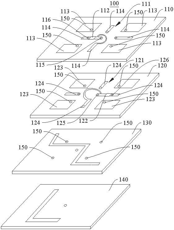
The invention provides a magnetoelectric dipole antenna structure and an antenna array, belonging to the technical field of microwave communication. According to the invention, a first antenna assembly and a second antenna assembly which have different polarization modes and are expressed by adopting patch type magnetoelectric dipole antennas are respectively installed on a first dielectric layer and a second dielectric layer, and a radio frequency circuit layer is electrically connected with the first antenna assembly and the second antenna assembly through the first antenna switch and the second antenna switch so as to realize feeding of the first antenna assembly and the second antenna assembly at the same time; and then, the on-off state of the first antenna switch and / or the second antenna switch is regulated and controlled through a digital circuit layer, so the respective operation states of the first antenna assembly and the second antenna assembly are adjusted, the polarization mode switching function of the antenna structure is realized, and multi-polarization of the antenna is conveniently realized; and meanwhile, the mechanical strength of the antenna structure is improved through a multi-layer structure composition mode. Therefore, the multi-polarization difficulty and the processing difficulty of antennas can be reduced, and antenna array realization is facilitated.

Description

technical field [0001] The present application relates to the technical field of microwave communication, in particular, to a magnetoelectric dipole antenna structure and an antenna array. Background technique [0002] With the continuous development of science and technology, microwave communication technology is more and more widely used in various industries, and people have put forward higher requirements for the signal transmission and reception performance of the antenna. Among them, the magnetoelectric dipole antenna has a wide operating frequency band and a wide axial ratio. Beamwidth, stable in-band gain flatness, stable unidirectional radiation pattern, and low cross-polarization have gained widespread attention in the field of microwave communications. For the magnetoelectric dipole antenna, the conventional magnetoelectric dipole antenna still has the problem that it is difficult to achieve multi-polarization, and the overall use of a three-dimensional structure ...

Claims


Application Information

Patent Timeline
Patent Type & Authority Applications(China)
IPC IPC(8): H01Q1/38H01Q1/50H01Q9/16H01Q15/24H01Q21/00H01Q21/24
CPCH01Q1/38H01Q1/50H01Q9/16H01Q15/24H01Q21/0006H01Q21/24
Inventor 许峰凯刘会奇郭凡玉吴祖兵
Owner CHENGDU T-RAY TECH CO LTD
Learn More