Manufacturing method of concrete spherical hinge with ultra-high performance

A concrete ball joint, ultra-high-performance technology, applied in construction, bridge construction, bridges, etc., can solve the problems of reduced reliability of ball joint rotation, great influence on the bearing capacity of ball joints, and difficulty in guaranteeing spherical surface processing accuracy, etc., to achieve improved Design pressure, save welding and inspection work, ensure the effect of stability and centering ability

Active Publication Date: 2021-08-17
ZHENGZHOU UNIV
View PDF6 Cites 0 Cited by
  • Summary
  • Abstract
  • Description
  • Claims
  • Application Information

AI Technical Summary

Problems solved by technology

The larger the size, the more difficult it is to guarantee the processing accuracy of the spherical surface, which makes the processing process of the spherical joint complex and high in technical content, and puts forward high requirements for the equipment capacity and comprehensive technical capacity of the manufacturer.
At the same time, it also increases the difficulty of transportation and on-site installation, especially during the concrete pouring process under the lower ball joint, it is easy to hold air and pour the concrete without compaction
[0005] On the other hand, the spherical surface of the lower ball hinge of the steel ball hinge needs to be installed with a circular non-metallic slide plate. Usually, the slide plate is inlaid on the spherical surface in a scattered shape. This method of fixing the slide plate is not reliable.
And there is a large gap between the slider and the slider, so that the contact area between the slider and the upper ball joint is small, the friction is large, and the reliability of the ball joint rotation is reduced.
At the same time, more grease is needed to fill the gap between the slides, and the bearing capacity of the ball joint is greatly affected by the bearing capacity of the slides

Method used


Image

  • Manufacturing method of concrete spherical hinge with ultra-high performance
  • Manufacturing method of concrete spherical hinge with ultra-high performance
  • Manufacturing method of concrete spherical hinge with ultra-high performance

Examples


Embodiment 1

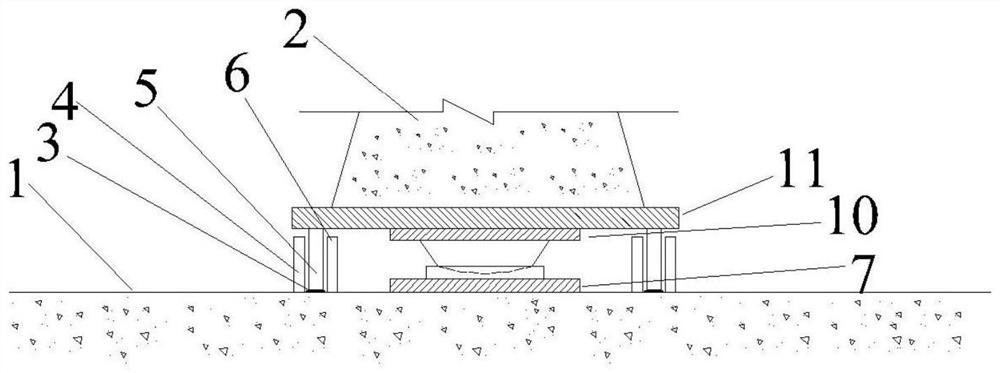
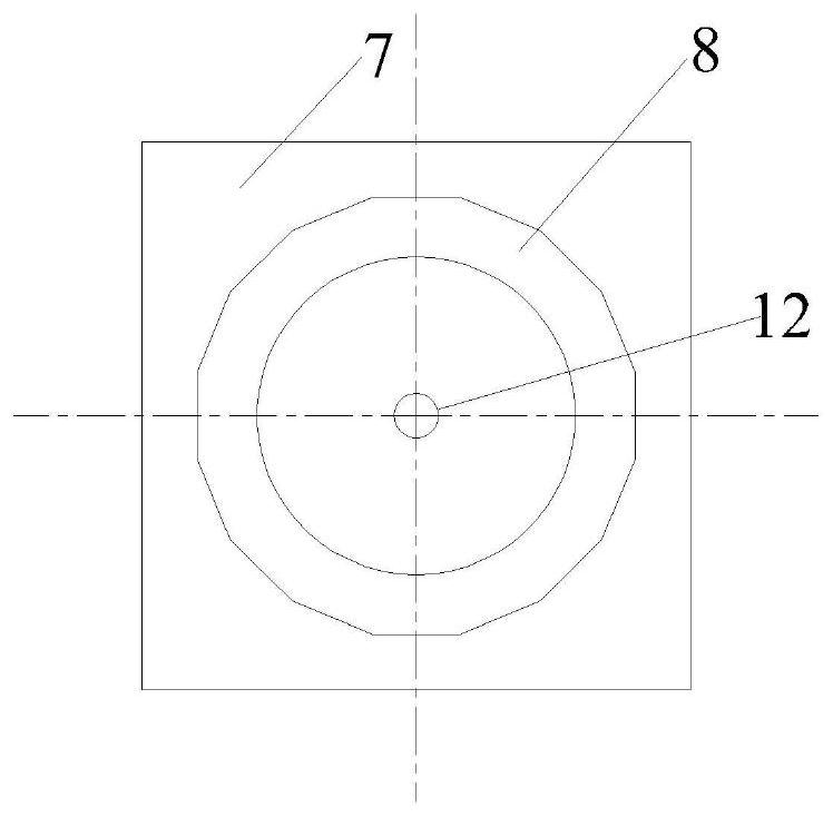
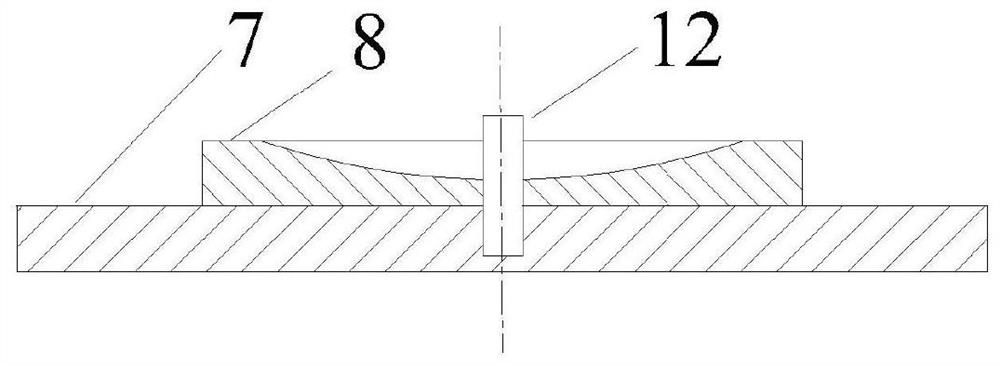
[0060] The schematic diagram of the position of the ball joint in the swivel device in this embodiment is shown in figure 1 , The surface layer of the lower ball joint is provided with 3 fiber orientation layers, the fibers in the middle layer are along the warp direction, and the fibers in the other two layers are along the weft direction (that is, the hoop direction). The spherical joint includes the upper spherical joint 9 and the lower spherical joint 8, both of which are made of steam-cured ultra-high performance concrete mixed with steel fibers. The 28-day compressive strength is greater than 150Mpa, the tensile strength is greater than 7.5Mpa, and the elastic modulus is greater than 40 GMPa. The diameter of the steel fiber is 0.2 mm and the length is 12 mm. Above the ball hinge is an inverted cone structure 13, an upper seat plate 10 is arranged between the inverted cone structure 13 and the turntable 11, and a lower seat plate 7 is arranged between the ball hinge and ...


PUM


Abstract

The invention relates to a manufacturing method of a concrete spherical hinge with ultra-high performance, and belongs to the field of civil construction engineering. Steel spherical hinges generally need to be customized in bridge swivel construction, but large-diameter steel spherical hinge assemblies are difficult to manufacture, transport and install, and the cost is high. According to the method for manufacturing the spherical hinge on site through the ultra-high performance concrete (UHPC), fibers are doped in the UHPC, the fibers on the upper surface of the lower spherical hinge are directionally arranged in a layered mode, and the bearing capacity of the spherical hinge is improved. According to the manufacturing method, steel is saved, a construction unit can complete manufacturing of the spherical hinge on a construction site, the transportation cost of the spherical hinge is saved, the manufacturing cost of the spherical hinge is reduced, the technical requirement is low, and the manufacturing cost is low.

Description

technical field [0001] The invention belongs to the technical field of civil engineering, and in particular relates to a manufacturing method of an ultra-high-performance concrete spherical joint. Background technique [0002] In recent years, the modern rapid transportation system has developed rapidly, and high-speed railways, dedicated passenger lines, and expressways are in the stage of large-scale construction. With the construction of high-speed railways and highways, a large number of large bridges have emerged one after another across deep trenches and canyons, across railways and highways. Due to the constraints of the construction environment and traffic factors, it is very difficult to adopt conventional construction methods for such bridges. The bridge swivel method can better avoid the impact on other lines of transportation, and overcome the difficulties of erecting long-span bridges on rivers with high mountains and canyons, deep water and fast currents, or f...

Claims


Application Information

Patent Timeline
Patent Type & Authority Applications(China)
IPC IPC(8): E01D21/00E01D21/08
CPCE01D21/00E01D21/08
Inventor 魏建东常天冰郝放张鹏刘杰陶志刚宁轩张书蕾
Owner ZHENGZHOU UNIV
Why Eureka
Try Eureka