Transfer mechanism for a split-cycle engine

An engine and transmission cavity technology, applied in the field of split cycle engines, can solve problems such as reducing efficiency, reducing compression ratio, and exhaust emissions.

Pending Publication Date: 2021-08-17
TOUR ENGINE INC
View PDF14 Cites 0 Cited by
  • Summary
  • Abstract
  • Description
  • Claims
  • Application Information

AI Technical Summary

Problems solved by technology

Additionally, conventional arrangements may only allow compression ratio reduction via valve timing (e.g. Miller and Atkinson cycles) and may be less efficient than increasing efficiency, which is not performed in a single cylinder for all four strokes. It is possible to place in a cycle engine
[0008] Another disadvantage of conventional internal combustion engines is the incomplete chemical combustion process, which reduces efficiency and leads to harmful exhaust emissions

Method used


Image

  • Transfer mechanism for a split-cycle engine
  • Transfer mechanism for a split-cycle engine
  • Transfer mechanism for a split-cycle engine

Examples


Embodiment Construction

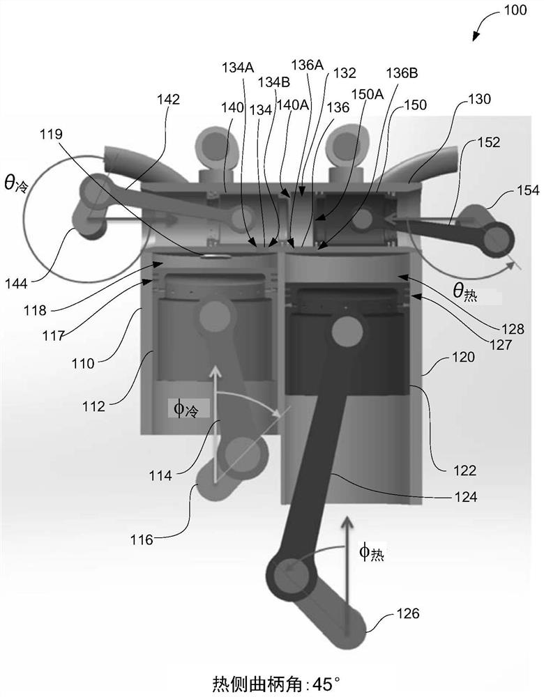
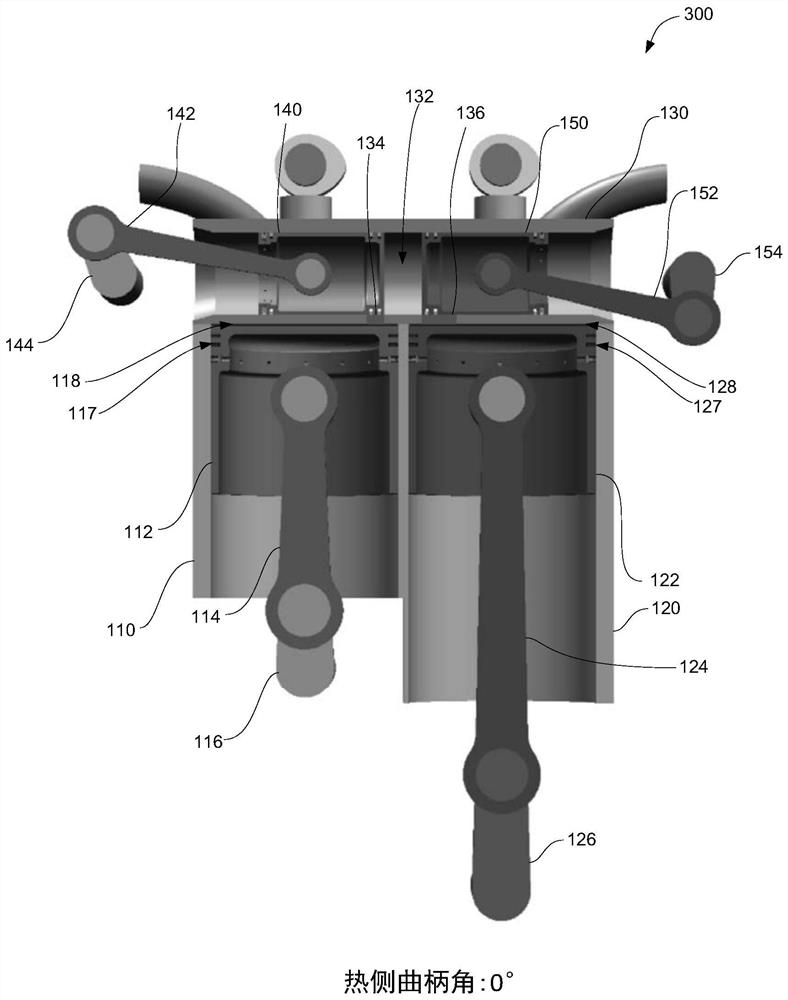
[0039] In view of the above-mentioned inherent disadvantages of known types of internal combustion engines now existing in the prior art, the embodiments described herein include split-cycle internal combustion engines having different cylinders. In some embodiments, the split-cycle internal combustion engines described herein having different cylinders more efficiently convert fuel energy into mechanical work, better control the amount of EGR, and enable reduced EGR in split-cycle engines. In some embodiments, the transfer cylinder facilitates more efficient and reliable transfer of working fluid from the compression chamber to the expansion chamber. In some embodiments, the transfer chamber includes two pistons that are relatively (e.g., laterally within the transfer chamber) movable to selectively fluidly couple the transfer chamber with the compression and expansion chambers (e.g., Movement of the two pistons causes the transfer chamber to be fluidly coupled to neither, on...


PUM


Abstract

A split-cycle engine includes: a compression chamber, housing a first piston, that induces and compresses working fluid; an expansion chamber, housing a second piston, that expands and exhausts the working fluid; and a transfer chamber, housing a third piston and a fourth piston, wherein the third piston and the fourth piston move relatively to vary a volume within the transfer chamber and to selectively fluidly couple the volume within the transfer chamber to the compression chamber and the expansion chamber. A method of operating an engine includes: inducing working fluid in a first chamber; compressing the working fluid in the first chamber; moving a first moveable boundary of a second chamber; moving a second moveable boundary of the second chamber; expanding the working fluid in the third chamber; and exhausting the working fluid from the third chamber.

Description

[0001] To all who may care: [0002] Note that we: Michael H. Wahl, Amit Helfand, Gilad Tour, Yehoram Hofman, Hugo Benjamin Tour, and Oded Tour have invented a new and useful transmission mechanism for split-cycle engines whose instructions are as follows: technical field [0003] The present disclosure relates generally to split-cycle engines, and in particular to systems and methods for regulating fluid flow between compression and expansion chambers of split-cycle engines. Background technique [0004] A conventional internal combustion engine consists of one or more cylinders. Each cylinder consists of a single piston that performs four strokes, commonly referred to as intake stroke, compression stroke, combustion / power / expansion stroke, and exhaust stroke. Together these four strokes form a complete cycle of the engine, performed during two complete revolutions of the crankshaft. Each part of the cycle is affected differently by the heat rejected from the working flui...

Claims


Application Information

Patent Timeline
Patent Type & Authority Applications(China)
IPC IPC(8): F02B41/06
CPCF02B41/06F02B33/22F02F1/242
Inventor M·H·瓦尔A·赫尔方德G·托尔Y·霍夫曼H·B·托尔O·托尔
Owner TOUR ENGINE INC
Why Eureka
Try Eureka