Eureka AIR delivers breakthrough ideas for toughest innovation challenges, trusted by R&D personnel around the world.

In-situ laser cleaning auxiliary tool for airplane

A laser cleaning and auxiliary tooling technology, which is applied in the field of laser cleaning, can solve problems such as surface damage, inability to meet high-quality cleaning and processing requirements, and inability to guarantee the consistency of processing results, etc.

Pending Publication Date: 2021-08-20
金顿激光科技(佛山)有限公司
View PDF0 Cites 0 Cited by
  • Summary
  • Abstract
  • Description
  • Claims
  • Application Information

AI Technical Summary

Problems solved by technology

[0004] The existing laser cleaning tools are mostly set as hand-held for the convenience of movement, but in the actual cleaning process, as the laser cleaning tool moves on the surface of the cleaning object, the distance between the laser light outlet and the surface of the cleaning object cannot be controlled, which makes The consistency of the processing effect cannot be guaranteed, some parts cannot be cleaned, and some parts even have surface damage, which cannot meet the needs of high-quality cleaning and processing

Method used


Image

  • In-situ laser cleaning auxiliary tool for airplane
  • In-situ laser cleaning auxiliary tool for airplane
  • In-situ laser cleaning auxiliary tool for airplane

Examples


Embodiment Construction

[0038] The principles and features of the present invention are described below in conjunction with the accompanying drawings, and the examples given are only used to explain the present invention, and are not intended to limit the scope of the present invention.

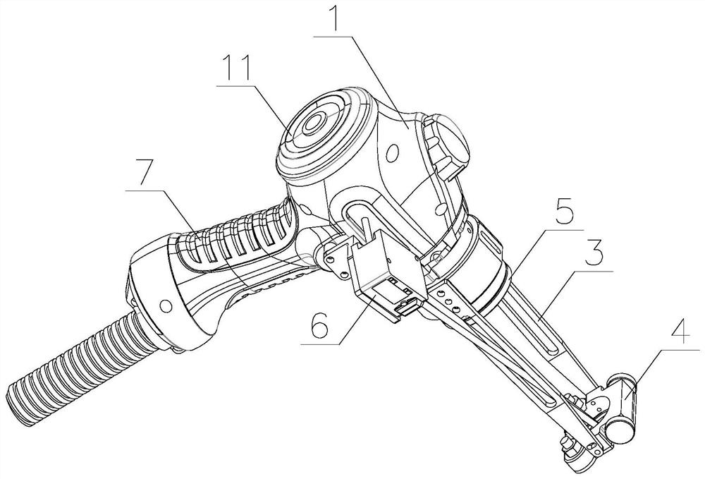
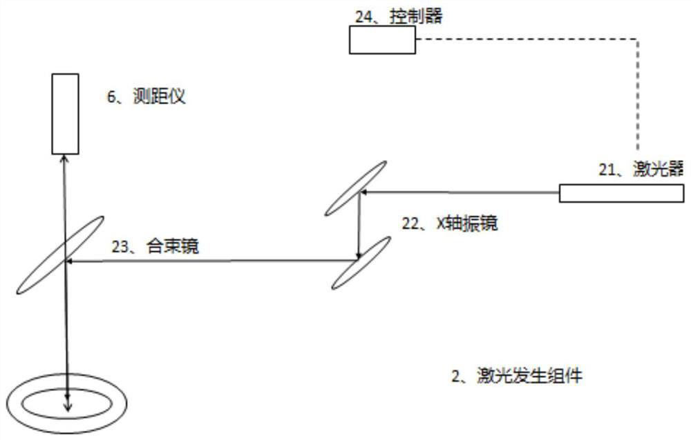
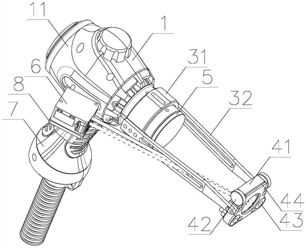
[0039] Such as figure 1 As shown, an aircraft in-situ laser cleaning auxiliary tooling includes a tooling body 1 with a hollow interior, a laser generating component 2, a support component 3 hollowed out in the middle, and a walking component 4. One end of the tooling body 1 is provided with a The laser generating assembly 2 is arranged in the tool body 1, and one end of the support assembly 3 is connected to the outer wall of the end of the tool body 1 where the light output hole is provided. The support assembly 3 The other end of the walking assembly 4 is installed, the middle part of the walking assembly 4 is provided with a through hole for the laser to pass through and irradiate the surface of the cleaning obj...


PUM


Abstract

The invention relates to an in-situ laser cleaning auxiliary tool for an airplane. The in-situ laser cleaning auxiliary tool comprises a tool body, a laser generating assembly, a supporting assembly with the hollowed-out middle and a walking assembly; a light outlet hole is formed in one end of the tool body; the laser generating assembly is arranged in the tool body; one end of the supporting assembly is connected with the outer wall of the end, provided with the light outlet hole, of the tool body; the walking assembly is installed at the other end of the supporting assembly; a through hole is formed in the middle of the walking assembly; and laser emitted by the laser generating assembly penetrates out of the light outlet hole and then sequentially irradiates the surface of a cleaned object through the through hole, and the surface of the cleaned object is cleaned when the walking assembly walks on the surface of the cleaned object. According to the in-situ laser cleaning auxiliary tool, the laser irradiates the surface of the cleaned object, the tool can conveniently move on the surface of the cleaned object through the walking assembly, and the labor intensity is lowered; and the distance between the light outlet hole and the surface of the cleaned object is constant through the supporting assembly, the cleaning site can be constant, the cleaning efficiency is improved, and the cleaning effect is guaranteed.

Description

technical field [0001] The invention relates to the technical field of laser cleaning, in particular to an aircraft in-situ laser cleaning auxiliary tooling. Background technique [0002] With the development of laser technology, laser has been widely used in various industries, among which the use of laser for cleaning is very common. Compared with traditional cleaning methods, laser cleaning is a "green" cleaning method that can avoid environmental pollution caused by chemical cleaning, and laser cleaning is a non-contact cleaning method that avoids mechanical damage to the surface of the cleaning object. At the same time, it is convenient to realize long-distance operation, with high cleaning efficiency and time saving. Therefore, more and more fields use laser for cleaning. [0003] In the service environment of the aircraft, metal corrosion is inevitable, which leads to local paint failure. In order to ensure the expected life of the aircraft, it is necessary to clean...

Claims


Application Information

Patent Timeline
Patent Type & Authority Applications(China)
IPC IPC(8): B08B7/00B08B13/00B64F5/30
CPCB08B7/0042B08B13/00B64F5/30
Inventor 刘顿洪洋任晋宇涂宣梦
Owner 金顿激光科技(佛山)有限公司
Why Eureka
Eureka Blog
Learn More