Tailor welding method for impeller rear disc of large centrifugal fan
A technology of impeller rear plate and centrifugal fan, which is applied in welding equipment, welding accessories, arc welding equipment, etc., can solve the problems of easy cracks due to stress concentration, large welding seam restraint, and large welding deformation, so as to reduce the restraint degree , reduce the probability of weld cracks, and reduce the effect of deformation
- Summary
- Abstract
- Description
- Claims
- Application Information
AI Technical Summary
Problems solved by technology
Method used
Image

Examples
Embodiment 1
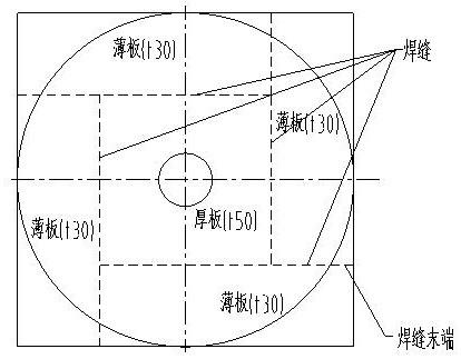
[0021] see figure 1 , the present invention provides the following technical solutions: a large centrifugal fan impeller rear disc tailor welding method, comprising the following steps:
[0022] A. Grind and clean the welding area of the thin plate of the impeller rear disc;
[0023] B. Put the cleaned sheet into an oven for drying;
[0024] C. Splicing and fixing the four dried impeller rear disk sheets with a positioning device;
[0025] D. Finally, weld the positioned impeller rear disk thin plate to form the centrifugal fan impeller rear disk.
[0026] In this embodiment, the drying temperature in step B is 80° C., and the drying time is 30 minutes.
[0027] In this embodiment, the application provides a tailor-welding method for the rear disc of a large centrifugal fan impeller, wherein the positioning device in step C adopts an I-shaped clamp.
[0028] In this embodiment, the application provides a large centrifugal fan impeller back plate tailor welding method, wh...
Embodiment 2
[0032] A large centrifugal fan impeller rear disk tailor welding method, comprising the following steps:
[0033] A. Grind and clean the welding area of the thin plate of the impeller rear disc;
[0034] B. Put the cleaned sheet into an oven for drying;
[0035] C. Splicing and fixing the four dried impeller rear disk sheets with a positioning device;
[0036] D. Finally, weld the positioned impeller rear disk thin plate to form the centrifugal fan impeller rear disk.
[0037] In this embodiment, the drying temperature in step B is 100° C., and the drying time is 40 minutes.
[0038] In this embodiment, the application provides a tailor-welding method for the rear disc of a large centrifugal fan impeller, wherein the positioning device in step C adopts an I-shaped clamp.
[0039] In this embodiment, the application provides a large centrifugal fan impeller back plate tailor welding method, wherein, in the step D, CO 2 Shielded welding.
[0040] In this embodiment, the a...
Embodiment 3
[0043] A large centrifugal fan impeller rear disk tailor welding method, comprising the following steps:
[0044] A. Grind and clean the welding area of the thin plate of the impeller rear disc;
[0045] B. Put the cleaned sheet into an oven for drying;
[0046] C. Splicing and fixing the four dried impeller rear disk sheets with a positioning device;
[0047] D. Finally, weld the positioned impeller rear disk thin plate to form the centrifugal fan impeller rear disk.
[0048] In this embodiment, the drying temperature in step B is 85° C., and the drying time is 32 minutes.
[0049] In this embodiment, the application provides a tailor-welding method for the rear disc of a large centrifugal fan impeller, wherein the positioning device in step C adopts an I-shaped clamp.
[0050] In this embodiment, the application provides a large centrifugal fan impeller back plate tailor welding method, wherein, in the step D, CO 2 Shielded welding.
[0051] In this embodiment, the ap...
PUM
 Abstract
Description
Claims
Application Information
 - R&D Engineer
- R&D Manager
- IP Professional
- Industry Leading Data Capabilities
- Powerful AI technology
- Patent DNA Extraction
Browse by: Latest US Patents, China's latest patents, Technical Efficacy Thesaurus, Application Domain, Technology Topic.
© 2024 PatSnap. All rights reserved.Legal|Privacy policy|Modern Slavery Act Transparency Statement|Sitemap