Copper pipe flaring device and method and copper pipe machining equipment

A technology for copper tubes and flaring components, used in metal processing equipment, feeding devices, positioning devices, etc., can solve the problems of easy shaking, low production and processing efficiency, low chamfering efficiency, etc., to achieve tight connection and improve production. Processing efficiency, the effect of improving efficiency

Inactive Publication Date: 2021-08-20
杜洋
View PDF8 Cites 0 Cited by
  • Summary
  • Abstract
  • Description
  • Claims
  • Application Information

AI Technical Summary

Problems solved by technology

[0005] 1. When the two ends of the copper tube are flaring at the same time, the copper tube is difficult to fix, and it is easy to shake, resulting in poor flaring quality
[0006] 2. Traditional copper pipe flaring equipment can only perform flaring and chamfering operations on the cut copper pipes, and the existing cutting device cannot directly match the flaring device, resulting in the need for different equipment for processing copper pipes, which affects Processing efficiency
[0007] 3. It is difficult to directly connect the cut copper tube with the flaring device, resulting in low production and processing efficiency
[0008] 4. The copper tube cannot be fed continuously during the chamfering process, resulting in low chamfering efficiency

Method used


Image

  • Copper pipe flaring device and method and copper pipe machining equipment
  • Copper pipe flaring device and method and copper pipe machining equipment
  • Copper pipe flaring device and method and copper pipe machining equipment

Examples


Embodiment Construction

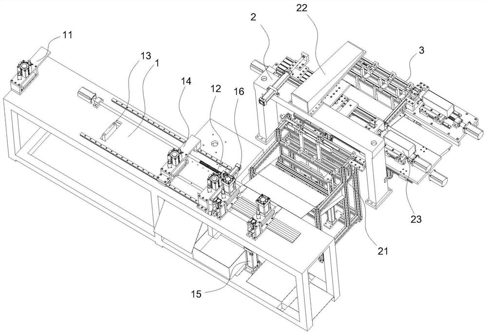
[0034] Such as figure 1As shown, a copper tube flaring and chamfering processing equipment includes a frame and a copper tube feeding and cutting device 1 , a flaring device 2 and a chamfering device 3 installed on the frame. Copper pipe feeding and cutting device 1, flaring device 2 and chamfering device 3 are arranged side by side. The discharge end of the copper tube feeding and cutting device 1 is connected to the flaring device 2 , and the discharge end of the flaring device 2 is connected to the chamfering device 3 . The copper pipe feeding and cutting device 1 is used for conveying the copper pipe and cutting the copper pipe to a fixed length and conveying the cut copper pipe to the flaring device 2 . The flaring device 2 is used for flaring the two ends of the copper pipe and transporting the flared copper pipe to the chamfering device 3 . The chamfering device 3 is used for chamfering one end of the copper pipe. The flaring device 2 is a kind of flaring device used...


PUM


Abstract

The invention relates to the field of copper pipe machining, in particular to a copper pipe flaring device and method and copper pipe flaring and chamfering machining equipment. The flaring device comprises a copper pipe storage rack, a copper pipe moving manipulator and a flaring mechanism. The copper pipe moving manipulator is arranged above the copper pipe storage rack, the flaring mechanism is arranged at one side of the copper pipe storage rack, and the flaring mechanism is connected with the copper pipe moving manipulator; the copper pipe storage rack is used for storing copper pipes; the copper pipe moving manipulator is used for grabbing the copper pipes in the copper pipe storage rack, moving the copper pipes into the flaring mechanism and moving the flaring copper pipes into a chamfering device; and the flaring mechanism is used for conducting flaring operation on the two ends of the copper pipes. When the copper pipes are flared, two groups of flaring clamping cylinders are used for respectively controlling two flaring clamping jaws, so that the two flaring clamping jaws are close to each other to clamp the copper pipes, then flaring operation is performed, the copper pipes are ensured not to shake during flaring, and the flaring quality is ensured.

Description

technical field [0001] The invention relates to the field of copper tube processing, in particular to a flaring device, method and copper tube processing equipment. Background technique [0002] In the field of mechanical processing, the processing of tube materials is more common, such as single-function or compound-function equipment for punching, punching or chamfering tube materials is also widely used. [0003] For example, the Chinese invention patent (publication number: CN107775341A, publication date: 20180309) discloses a flaring chamfering machine, which belongs to the technical field of pipe material processing and is designed for the integration of pipe material flaring and chamfering processing, including a workbench, The workbench is provided with a feeding mechanism for feeding the pipe material, a grasping mechanism for grabbing and moving the pipe material, and a clamping and positioning mechanism for clamping and positioning the pipe material , a flaring m...

Claims


Application Information

Patent Timeline
Patent Type & Authority Applications(China)
IPC IPC(8): B23P23/04B23Q7/14B23D45/12B23D47/04B21D41/02B21D43/00B21D43/02
CPCB23P23/04B23Q7/14B23D45/12B23D47/042B21D41/02B21D43/003B21D43/006B21D43/02
Inventor 杜洋黄震南童辉赵桂林
Owner 杜洋
Why Eureka
Try Eureka