Automatic angle iron mounting equipment and method
An automatic installation and base coding technology, which is applied in stone processing equipment, lifting equipment in mines, transportation and packaging, etc., can solve problems such as strict installation requirements, heavy installation workload, and construction hazards, and achieve the elimination of danger and high precision High, the effect of improving construction efficiency
- Summary
- Abstract
- Description
- Claims
- Application Information
AI Technical Summary
Problems solved by technology
Method used
Image

Examples
Embodiment 1
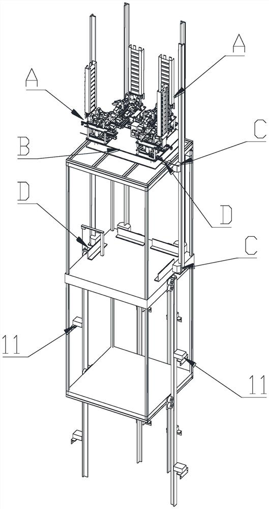
[0042] see Figure 1-Figure 17 , The automatic elevator guide rail installation equipment of the present invention includes a lifting box B, an automatic bottom code installation device A arranged on the lifting box B, a guide rail handling device C and a distance measuring device D.
[0043] The specific structures of the bottom code automatic installation device A, the lifting box B, the guide rail conveying device C and the distance measuring device D are described in detail below.
[0044] (1) Lifting box B
[0045] see Figure 1-Figure 17, the lifting box B is located in the shaft, and the lifting box B has at least a two-layer structure, and different automatic construction modules and part of the space can be arranged according to needs for manual work; wherein, the bottom code is automatically The installation device A is multiple groups, and the multi-group bottom code automatic installation device A is installed on the upper platform of the lifting box B; the upper...
Embodiment 2
[0094] see Figure 1-Figure 17 , the present invention utilizes automatic construction work to install the guide rail and the basic fastener of the door cover in the elevator shaft, and its construction work method is as follows: Including the auxiliary construction equipment required by the construction personnel for installation)
[0095] (1) Measuring the shaft, installing the plumb line of the guide rail and the door casing
[0096] Measure the well to confirm whether the wall of the well is out of tolerance in size or verticality, and whether it needs to be rectified to meet the construction standard requirements.
[0097] Install the plumb line of the guide rail and the door casing. The plumb line is usually stretched along the plumb direction with a piano wire with a diameter of 0.5-1mm and fixed at both ends of the bottom and top of the well. The plumb line includes the left and right sides of the door casing along the The plumb line on the inner side of the door fra...
Embodiment 3
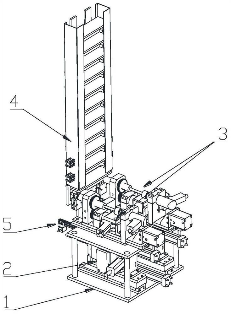
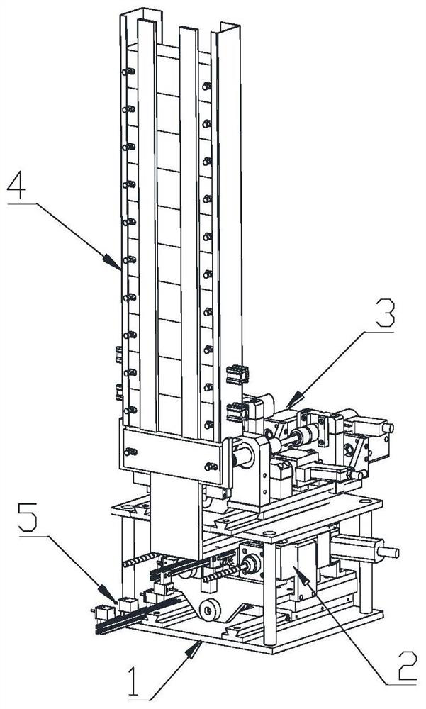
[0114] see Figure 18-Figure 22 , the difference between this embodiment and embodiment 1 is:
[0115] The guide rail conveying device C includes a guide rail alignment movement mechanism 8 arranged on the lift box B for transporting the guide rail to the corresponding guide rail support, wherein the guide rail alignment movement mechanism 8 includes a guide rail alignment movement mechanism 8 arranged on the lift box body The guide rail holder for clamping the guide rail on the platform of B and the guide rail transport driving mechanism for driving the guide rail holder to move to the guide rail bracket; wherein,
[0116] The guide rail clamping part includes a first clamping part 8-6 and a second clamping part 8-1 arranged on the lifting platform of the lifting box B, wherein the second clamping part 8-1 is arranged on The lifting box B is located on the lifting platform below the first clamping part 8-6, wherein the first clamping part 8-6 is an electromagnetic gripper, a...
PUM
 Abstract
Description
Claims
Application Information
 - R&D
- Intellectual Property
- Life Sciences
- Materials
- Tech Scout
- Unparalleled Data Quality
- Higher Quality Content
- 60% Fewer Hallucinations
Browse by: Latest US Patents, China's latest patents, Technical Efficacy Thesaurus, Application Domain, Technology Topic, Popular Technical Reports.
© 2025 PatSnap. All rights reserved.Legal|Privacy policy|Modern Slavery Act Transparency Statement|Sitemap|About US| Contact US: help@patsnap.com