Wire clamp cleaning and conductive paste smearing integrated processing device

A processing device and conductive paste technology, applied in the direction of circuit/collector parts, circuits, electrical components, etc., can solve the problems of low efficiency, irregular construction, labor consumption, etc., to solve low efficiency, improve maintenance efficiency, Improve the effect of smearing

Active Publication Date: 2021-08-20
JINHUA POWER TRANSMISSION & DISTRIBUTION ENG +1
View PDF4 Cites 0 Cited by
  • Summary
  • Abstract
  • Description
  • Claims
  • Application Information

AI Technical Summary

Problems solved by technology

The main reasons for the poor connection of the drainage components include three aspects: First, under the long-term influence of external environmental factors, the bolts between the drainage plate and the clamp are loosened
The second is that the wire clip has been in a relatively harsh outdoor environment for a long time, and the metal contact surface is oxidized, resulting in an increase in contact resistance and heat generation, resulting in failure
The third is that the construction is not standardized during the installation of these related components
This treatment method can effectively eliminate the heating defects of the contact surface, but there are still problems such as low surface polishing efficiency, uneven contact surface polishing, uneven conductive paste coating, and manual polishing by maintenance personnel, which is labor-intensive and inefficient. High, and there are great potential safety hazards in the operation of on-site workers. At the same time, due to the negligence of the judgment of the maintenance personnel, problems that cannot be found will also be caused.

Method used


Image

  • Wire clamp cleaning and conductive paste smearing integrated processing device
  • Wire clamp cleaning and conductive paste smearing integrated processing device
  • Wire clamp cleaning and conductive paste smearing integrated processing device

Examples


Embodiment Construction

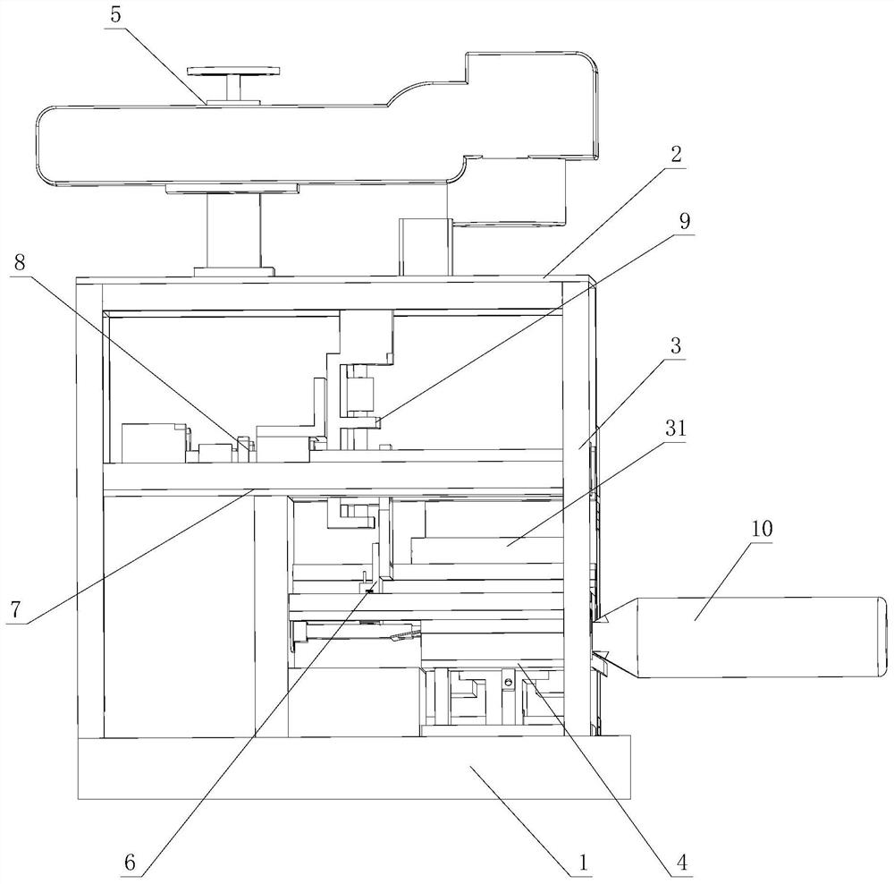
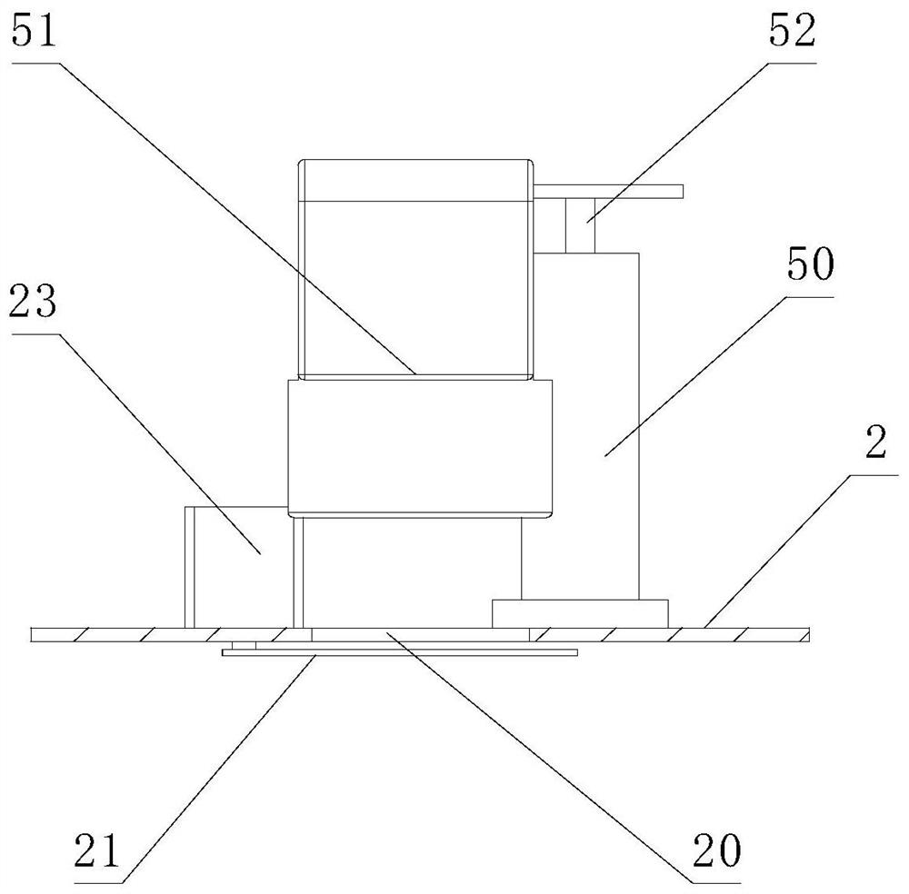
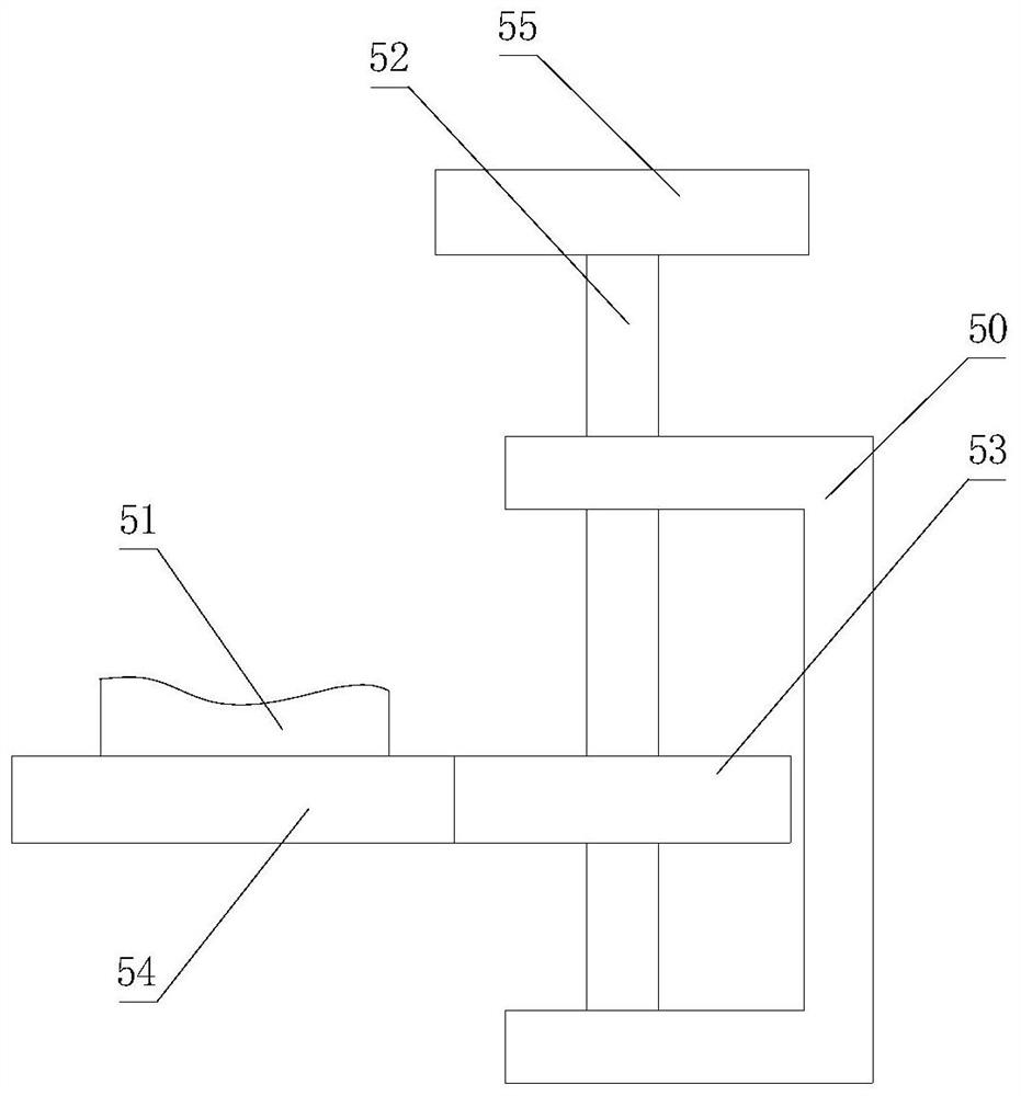
[0033] Such as figure 1 , figure 2 , image 3 , Figure 4 , Figure 5 , Figure 6 , Figure 7 , Figure 8 , Figure 9 , Figure 10 , Figure 11 , Figure 12 As shown, the integrated processing device for wire clamp cleaning and conductive paste application includes a bottom plate 1, a top plate 2 and a connecting rod 3 arranged between the bottom plate 1 and the top plate 2, and the bottom plate 1 is provided with a clamping mechanism for fixing the wire clamp 4. The top plate 2 is provided with a laser cleaning part 5 and an irradiation hole 20 for laser irradiation. The connecting rod 3 is movably connected with a feeding mechanism 6 for spraying conductive paste to the wire clip, and the feeding mechanism 6 is located at Between the clamping mechanism 4 and the top plate 2, the bottom end of the feeding mechanism 6 is provided with a scraper 60 that evenly coats the conductive paste on the wire clamp, and the feeding mechanism 6 is provided with a device for dete...


PUM


Abstract

The invention relates to a wire clamp cleaning and conductive paste smearing integrated processing device. The device comprises a bottom plate, a top plate and a connecting rod, the bottom plate is provided with a clamping mechanism, the top plate is provided with a laser cleaning part and an irradiation hole facilitating laser irradiation, the connecting rod is movably connected with a feeding mechanism, and the bottom end of the feeding mechanism is provided with a scraping plate for evenly coating a wire clamp with conductive paste. The device has the advantages that a wire clamp needing to be processed is fixed to the bottom plate through the clamping mechanism, then laser is emitted to the wire clamp through the laser cleaning part, conductive paste is sprayed to the surface of the cleaned wire clamp through the feeding mechanism after cleaning, and the wire clamp can be uniformly coated with the conductive paste due to the fact that the bottom end of the feeding mechanism is provided with the scraper for evenly coating the wire clamp with the conductive paste, so the device ensures the uniformity of conductive paste smearing, realizes the integrated treatment of wire clamp cleaning and conductive paste smearing, reduces the steps of manual operation, and greatly improves the efficiency.

Description

technical field [0001] The invention relates to an integrated processing device for wire clip cleaning and conductive paste application. Background technique [0002] Among the various electric fittings in the substation, the wire clip is used to connect the fixed lead wires, and there are wire clips in all the lead wires. It is widely used in the substation. Loose bolts at the wire clips will lead to poor connection of the drainage parts. If the load of the line increases, the temperature of the bad connection will rise rapidly, and a vicious circle will be generated, which will lead to more serious defects of the wire clips, and eventually thermal damage will occur. Due to the huge stock of wire clips in the substation, the wire clips The equipment failure caused by it has gradually become a common problem affecting the normal operation of substations in my country, and in the case of large-load single-circuit power supply, it is especially prone to power grid accidents such...

Claims


Application Information

Patent Timeline
Patent Type & Authority Applications(China)
IPC IPC(8): H01R43/00
CPCH01R43/00H01R43/002
Inventor 马宇辉程军程辉阳冯勇兵毛水强陈益坪林俊岑吴良建郑恒柳毅高晓旺马骁郑豪金斌彬方琪
Owner JINHUA POWER TRANSMISSION & DISTRIBUTION ENG
Why Eureka
Try Eureka