
Urban rail vehicle brake cylinder pressure control method and system

A brake cylinder pressure and control method technology, applied in the direction of brakes, vehicle components, pneumatic brakes, etc., can solve the problems of long pressure response lag time, pressure exceeding precision, and affecting the service life of valves, so as to reduce the difficulty of control and reduce The number of valve operations and the effect of improving control reliability

Active Publication Date: 2021-08-24
QINGDAO SRI TECH CO LTD
View PDF12 Cites 3 Cited by
  • Summary
  • Abstract
  • Description
  • Claims
  • Application Information

AI Technical Summary

Problems solved by technology

[0007] The present invention aims at the technical problems of long pressure response lag time caused by the above-mentioned existing methods, the pressure exceeds the precision requirement and affects the service life of the valve, and proposes a brake cylinder pressure control method and system for urban rail vehicles

Method used


Image

  • Urban rail vehicle brake cylinder pressure control method and system
  • Urban rail vehicle brake cylinder pressure control method and system
  • Urban rail vehicle brake cylinder pressure control method and system

Examples


Embodiment 1

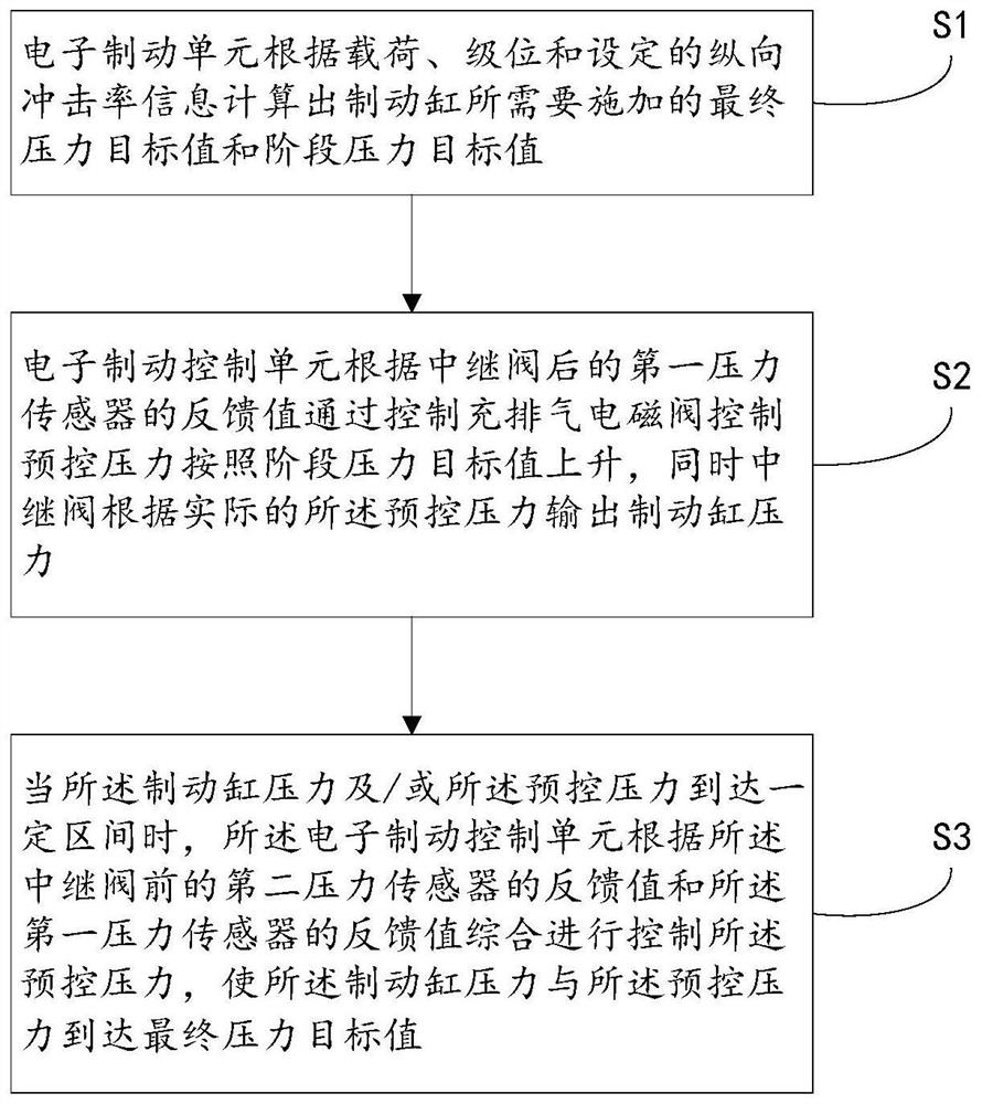
[0052] Such as figure 1 As shown, this embodiment discloses a specific implementation of a brake cylinder pressure control method for an urban rail vehicle (hereinafter referred to as "method").

[0053] Specifically, the method disclosed in this embodiment mainly includes the following steps:

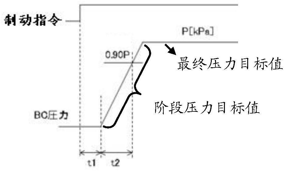
[0054] Step S1: The electronic brake control unit calculates the final pressure target value and stage pressure target value required by the brake cylinder according to the load, level and the set longitudinal impact rate information;

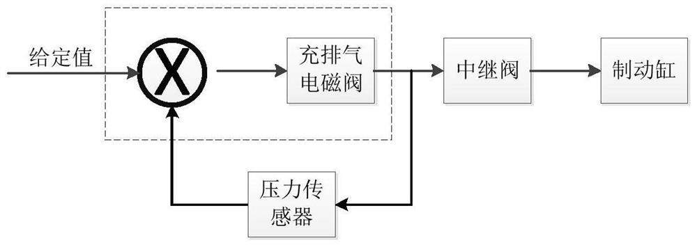
[0055] Step S2: According to the feedback value of the first pressure sensor behind the relay valve, the electronic brake control unit controls the pre-control pressure to rise according to the stage pressure target value by controlling the charging and exhaust solenoid valve, and the relay valve is based on the actual pre-control pressure. The pressure outputs the brake cylinder pressure; wherein, the first pressure sensor collects the brake cylinder ...

Embodiment 2

[0084] In combination with the brake cylinder pressure control method for urban rail vehicles disclosed in Embodiment 1, this embodiment discloses a specific implementation example of a brake cylinder pressure control system for urban rail vehicles (hereinafter referred to as "system").

[0085] The system includes:

[0086] Electronic brake control unit: Calculate the final pressure target value and stage pressure target value that the brake cylinder needs to apply according to the load, level and set longitudinal impact rate information;

[0087] The first pressure sensor: used to feed back the pressure value of the brake cylinder behind the relay valve to the electronic brake control unit;

[0088] The second pressure sensor: used to feed back the pre-control pressure value before the relay valve to the electronic brake control unit;

[0089] Filling and exhausting solenoid valve: used to convert the compressed air output of the air storage cylinder into the pre-control pr...


PUM


Abstract

The invention discloses an urban rail vehicle brake cylinder pressure control method and system, and the method comprises the steps that an electronic brake control unit controls the pre-control pressure to rise according to a stage pressure target value by controlling an inflation and exhaust electromagnetic valve according to a feedback value of a first pressure sensor behind a relay valve; meanwhile, the relay valve outputs the brake cylinder pressure according to the actual pre-control pressure; when the brake cylinder pressure and / or the pre-control pressure reach a certain interval, the electronic brake control unit comprehensively controls the pre-control pressure according to the feedback value of the second pressure sensor in front of the relay valve and the feedback value of the first pressure sensor, so that the brake cylinder pressure and the pre-control pressure reach the final pressure target value. The slow pressure response can be effectively avoided, and the valve action frequency and the control difficulty are reduced.

Description

technical field [0001] The invention relates to the technical field of locomotive braking control, in particular to a method and system for controlling the brake cylinder pressure of an urban rail vehicle. Background technique [0002] Urban rail transit vehicles need a safe and reliable braking system to ensure punctuality, comfort and safety. The braking system includes functions such as normal braking, emergency braking, holding braking, and ramp start, among which the most commonly used function is normal braking for normal entry and exit parking. [0003] For the urban rail brake control system, the pneumatic brake control unit in the brake control device controls the charge and exhaust valves to release the compressed air in the air storage cylinder according to the electrical signal sent by the EBCU (Electronic Brake Control Unit) The output is converted into the pre-control pressure corresponding to the electrical signal, and then the pre-control pressure is amplifi...

Claims


Application Information

Patent Timeline
Patent Type & Authority Applications(China)
IPC IPC(8): B60T13/68B61H11/06
CPCB60T13/683B61H11/06
Inventor 孙全涛郗开冲杜振振徐逸煌
Owner QINGDAO SRI TECH CO LTD
Learn More