Clamping and positioning mechanism ofintelligent sewing machine for sewing two pieces of cloth
A clamping positioning and sewing machine technology, applied in the field of sewing machines, can solve the problems of lack of omnidirectional clamping and positioning, mechanical injury of sewing personnel, and complicated operation.
- Summary
- Abstract
- Description
- Claims
- Application Information
AI Technical Summary
Problems solved by technology
Method used
Image
Examples
Embodiment 1
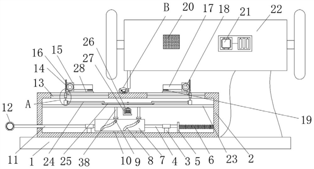
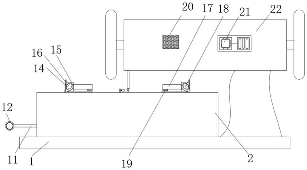
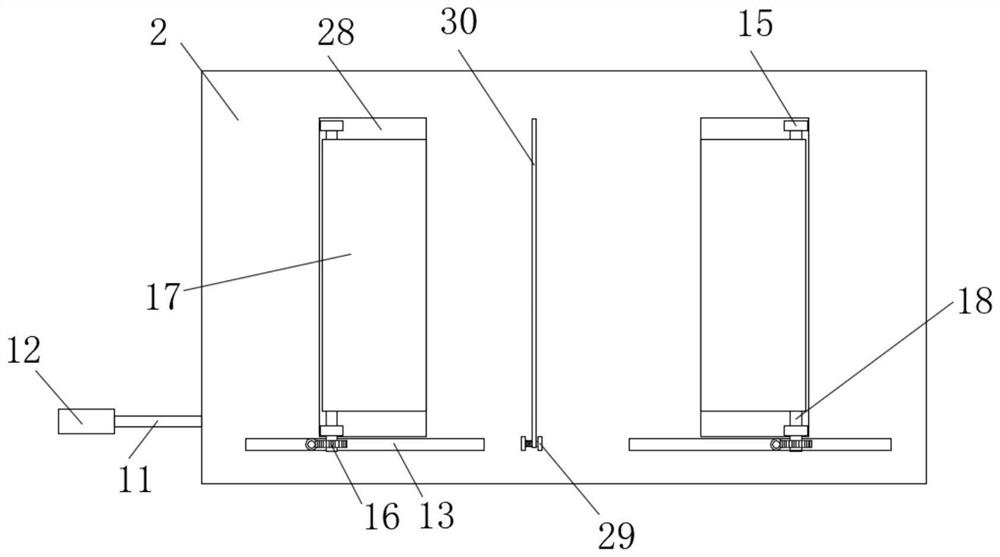
[0029] refer to Figure 1-7 , a clamping and positioning mechanism for double-piece cloth sewing of an intelligent sewing machine, comprising a platen 1, a clamping and positioning box 2 is slidably connected to the platen 1, and two mounting plates are symmetrically slidably connected to the top outer wall of the clamping and positioning box 2 28, two mounting plates 28 are provided with a clamping assembly, the inner wall of the clamping positioning box 2 is slidably connected with a sliding plate 23, and the sliding plate 23 is provided with an adjustment assembly for adjusting the distance between the two mounting plates 28, and the clamping positioning box 2 is provided with a sliding assembly that drives the sliding plate 23 to slide, and the top of the clamping and positioning box 2 is provided with a pressing assembly for pressing and positioning the suture parts of the two pieces of cloth. The top of the table 1 is fixed with an intelligent sewing machine main body 22,...
Embodiment 2
[0031]This embodiment is improved on the basis of Embodiment 1: the clamping assembly includes two first fixed blocks 15 that are symmetrically fixedly connected to the top of the mounting plate 28, and the sides of the two first fixed blocks 15 that are close to each other are rotatably connected with the same A rotating shaft 18, the outer wall of the rotating shaft 18 is fixedly covered with a rotating plate 17, the bottom of the rotating plate 17 is fixedly connected with a rubber plate 19, and the adjustment assembly includes a second L-shaped fixed plate 27 fixedly connected to the bottom of the sliding plate 23, the second A motor 26 is fixedly arranged on the L-shaped fixed plate 27, and the output shaft of the motor 26 runs through the slide plate 23 and is fixedly sleeved with a rotating rod 25. Both sides of the top of the rotating rod 25 are rotatably connected with a connecting rod 24, two connecting rods 24 One end far away from each other is rotatably connected w...
Embodiment 3
[0033] This embodiment is improved on the basis of Embodiment 1: the slide assembly includes two spacer rings 3 that are symmetrically and fixedly connected to the inner wall of the bottom of the clamping positioning box 2, and the inner walls of the two spacer rings 3 are respectively slidably connected with a first slide. The bar 4 and the second slide bar 11, the side of the first slide bar 4 and the second slide bar 11 close to each other are fixedly connected with the same rectangular plate 7, and the rectangular plate 7 is symmetrically provided with two curved grooves 8 for clamping The inner wall of the bottom of the positioning box 2 is symmetrically fixedly connected with two first L-shaped fixed plates 10, the first L-shaped fixed plate 10 runs through and is slidably connected with a push rod 38, and one side of the push rod 38 is fixedly connected with the inner wall of the curved groove 8 Slidingly connected bump 9, the first slide bar 4 is fixedly connected with ...
PUM
 Abstract
Description
Claims
Application Information
 - R&D
- Intellectual Property
- Life Sciences
- Materials
- Tech Scout
- Unparalleled Data Quality
- Higher Quality Content
- 60% Fewer Hallucinations
Browse by: Latest US Patents, China's latest patents, Technical Efficacy Thesaurus, Application Domain, Technology Topic, Popular Technical Reports.
© 2025 PatSnap. All rights reserved.Legal|Privacy policy|Modern Slavery Act Transparency Statement|Sitemap|About US| Contact US: help@patsnap.com


