
Self-locking air cylinder

A cylinder, self-locking technology, applied in the direction of fluid pressure actuating devices, can solve problems such as locking, and achieve the effects of scientific design, strong practicability and simple structure

Pending Publication Date: 2021-08-24
乐清市恒一气动有限公司
View PDF1 Cites 0 Cited by
  • Summary
  • Abstract
  • Description
  • Claims
  • Application Information

AI Technical Summary

Problems solved by technology

[0008] The purpose of the present invention is to provide a self-locking cylinder, which works in conjunction with the main cylinder by setting an auxiliary cylinder on the side. Through ingenious structural design, its locking and delay can be effectively and precisely controlled, avoiding the need for existing locking cylinders. Interference between the self-locking mechanism and the piston rod of the cylinder leads to the problem of locking

Method used


Image

  • Self-locking air cylinder
  • Self-locking air cylinder
  • Self-locking air cylinder

Examples


Embodiment 1

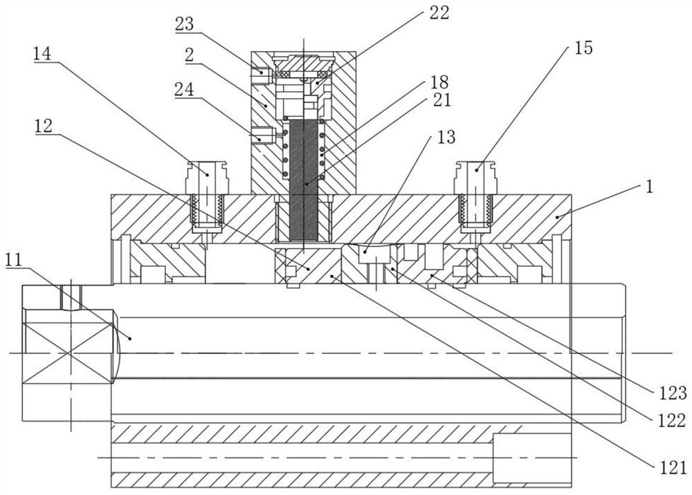
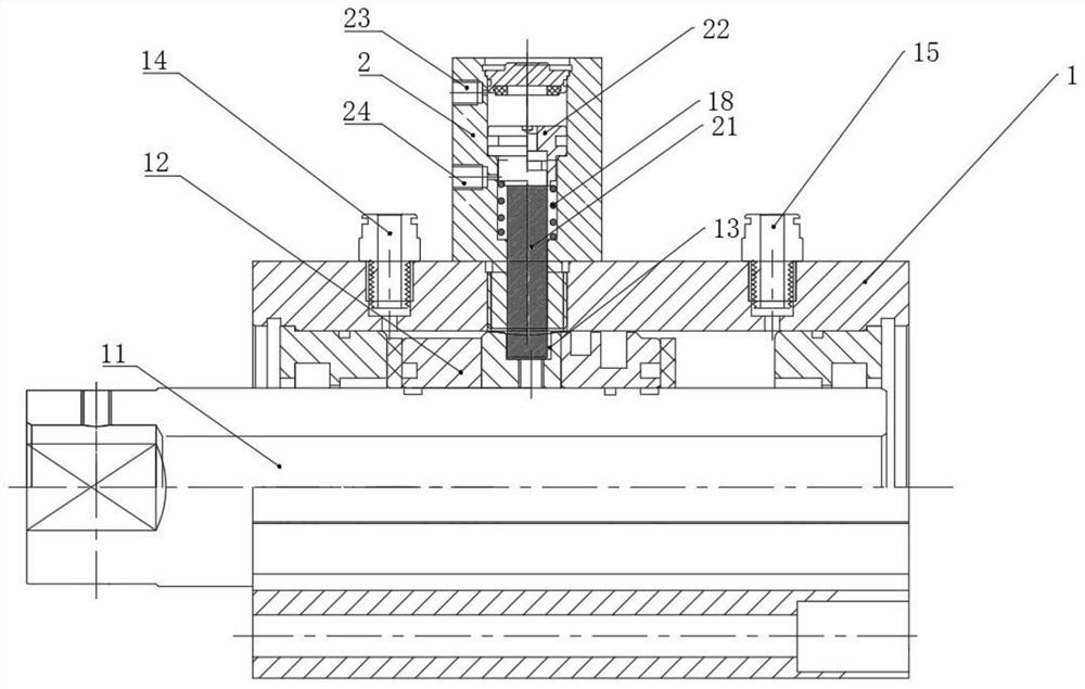
[0034] Example 1: The working principle of this solution product used on the button sewing machine

[0035] The working process of the traditional button sewing machine is generally produced by upper and lower double cylinders. The pressure of the upper cylinder is generally greater than that of the lower cylinder, and the lower cylinder also needs to lower the button based on the telescopic load, so that the upper and lower buttons can be pressed together. Before that, the radial setting The scheme of the auxiliary cylinder often has the problem of not locking up and down in time, resulting in incomplete upper and lower pressing, and not timely unlocking, resulting in jamming or equipment damage. However, the self-locking cylinder of this scheme has a simple structure and ingenious design. The main cylinder 1 is also equipped with an auxiliary cylinder 2. , the difference is that the auxiliary cylinder 2 of this program is provided with double air intake holes and a damping sp...

Embodiment 2

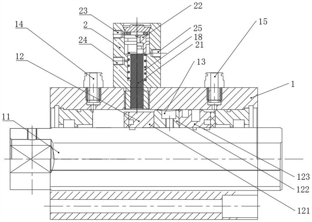
[0039] The working process of the traditional button sewing machine is generally produced by upper and lower double cylinders. The pressure of the upper cylinder is generally greater than that of the lower cylinder, and the lower cylinder also needs to lower the button based on the telescopic load, so that the upper and lower buttons can be pressed together. Before that, the radial setting The scheme of the auxiliary cylinder often has the problem of not locking up and down in time, resulting in incomplete upper and lower pressing, and not timely unlocking, resulting in jamming or equipment damage. However, the self-locking cylinder of this scheme has a simple structure and ingenious design. The main cylinder 1 is also equipped with an auxiliary cylinder 2. , the difference is that the auxiliary cylinder 2 of this program is provided with three air inlets and is provided with a damping spring 18 and has a set of ingenious gas circuit connection. If the air pump is used to suppl...


PUM


Abstract

The invention discloses a self-locking air cylinder which is characterized in that the self-locking air cylinder comprises a main air cylinder and an auxiliary air cylinder, wherein the main air cylinder comprises a piston rod, a fourth air inlet hole and a third air inlet hole ,wherein the fourth air inlet hole and the third air inlet hole drive the piston rod to do axial reciprocating motion, and the auxiliary air cylinder is arranged on the side face of the main air cylinder and comprises a self-locking rod with a first piston; one end of the self-locking rod extends into the main air cylinder and is matched, inserted and clamped with an annular groove formed in the piston rod to be used for self-locking the piston rod, and the auxiliary air cylinder is further provided with a first air inlet hole and a second air inlet hole which are located in the two ends of an inner cavity of the auxiliary air cylinder respectively and used for driving the self-locking rod to do axial reciprocating motion; the first piston is located between the first air inlet hole and the second air inlet hole to isolate the first air inlet hole and the second air inlet hole in an airtight mode and driven by air inflow of the first air inlet hole and the second air inlet hole to move axially. the self-locking air cylinder further comprises a damping spring which is positioned in the auxiliary cylinder. Compared with an existing air cylinder, the self-locking air cylinder is simple in structure, scientific in design and high in practicability, and has the functions of avoiding the phenomenon of mutual interference and jamming and locking the piston rod in a delayed mode.

Description

technical field [0001] The invention relates to the technical field of cylinders, in particular to a self-locking cylinder. Background technique [0002] There are many stations in the automation industry that require the cylinder to lock itself after it is raised to the right position, and wait for the next process station to press down. The cylinder increases its bearing capacity after self-locking. Normally, an automation equipment requires multiple cylinders to work together. [0003] At present, the status of self-locking cylinders on the market: ① Increase the bearing capacity by increasing the cylinder diameter, but the disadvantages are high energy consumption, high cost, and slow speed; In the way of spring filling, the auxiliary cylinder cannot be guaranteed to be opened first and often jams during the return process of the main cylinder. The disadvantage is obvious; The working radial rod of the cylinder is locked to prevent the movement of the main rod of the ma...

Claims


Application Information

Patent Timeline
Patent Type & Authority Applications(China)
IPC IPC(8): F15B15/14F15B15/26
CPCF15B15/1461F15B15/1452F15B15/1423F15B15/26
Inventor 朱乐飞陈建松虞金泽
Owner 乐清市恒一气动有限公司
Features
  • Generate Ideas
  • Intellectual Property
  • Life Sciences
  • Materials
  • Tech Scout
  • Unparalleled Data Quality
  • Higher Quality Content
  • 60% Fewer Hallucinations
Learn More