Coupling method of optical receiving sub-module of multiplexing optical module

An optical receiving sub-module and multiplexing light technology, applied in the field of coupling, can solve the problems of difficult coupling, high operation difficulty, complex process, etc., and achieve the effects of improving performance and yield, improving coupling efficiency, and simple operation

Active Publication Date: 2021-08-24
武汉英飞光创科技有限公司
View PDF8 Cites 1 Cited by
  • Summary
  • Abstract
  • Description
  • Claims
  • Application Information

AI Technical Summary

Problems solved by technology

This coupling method requires an external high-speed lens and prism, the equipment structure is complex, the cost is high, and the coupling is difficult
[0005] The position of the collimated light in the traditional coupling lens 2 depends on the calibration of the machine, to be precise, it depends on the fixed position of the high-speed lens. If there is a deviation in the fixed position of the high-speed lens, the coupled collimated light will also have deviations, so that Affects the coupling efficiency of light coupled into the PD by subsequent lens 1
[0006] The position of the collimated light in the traditional coupling lens 2 method also depends on the position of the shell assembly on the coupling table. If there is a deviation in the assembly of the shell on the coupling table, the final collimated light path will also have deviations, which will affect the subsequent lens. 1Coupling efficiency of light coupled into PD
[0007] After the traditional coupling method, lens 2 is coupled to lens 1. Since the position of PD has been fixed at this time, the position of PD relative to the collimated light has also been determined, so the relative position deviation between PD and collimated light directly affects the final coupling into PD. The light coupling efficiency of
[0008] Generally speaking, the traditional coupling method has very high requirements for equipment calibration, component placement accuracy and staff operation, and the process is relatively complicated and difficult to operate.
In addition, the coupling equipment is also more complicated, requiring two types of equipment for coupling collimated light (coupling lens 2) and coupling lens 1, and the cost is relatively high

Method used


Image

  • Coupling method of optical receiving sub-module of multiplexing optical module
  • Coupling method of optical receiving sub-module of multiplexing optical module
  • Coupling method of optical receiving sub-module of multiplexing optical module

Examples


Embodiment Construction

[0037] The following will clearly and completely describe the technical solutions in the embodiments of the present invention with reference to the accompanying drawings in the embodiments of the present invention. Obviously, the described embodiments are only some, not all, embodiments of the present invention. Based on the embodiments of the present invention, all other embodiments obtained by persons of ordinary skill in the art without making creative efforts belong to the protection scope of the present invention.

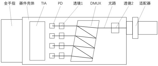
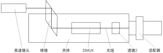
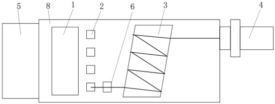
[0038] see figure Figure 3 to Figure 6, the embodiment of the present invention provides a coupling method of a multiplexing optical module optical receiving sub-module, including the following steps: S1, fixing the TIA 1, PD 2 and DMUX 3 on the housing 8; S2, fixing the TIA to the TIA 1 and the PD 2 with a gold wire, and power the TIA 1 and the PD 2 through the gold finger 5 of the housing 8; S3, connect an adapter with a collimator to the housing 8 and Con...


PUM


Abstract

The invention relates to a coupling method of an optical receiving sub-module of a multiplexing optical module. The coupling method comprises the following steps: S1, a TIA, a PD and a DMUX are fixed on a shell; S2, gold wires are bonded to the TIA and the PD, and the TIA and the PD are powered up through the golden fingers of the shell; s3, an adapter with a collimator is externally connected to the shell, and a light source is connected to the adapter; s4, one path is selected for coupling, the position of one first lens is adjusted firstly, then the position of the adapter is adjusted, then the position of the first lens is adjusted, the positions of the first lens and the adapter are adjusted repeatedly and circularly, and adjustment is stopped until the responsivity of the PD is no longer remarkably increased; s5, the adapter with the collimator is removed, and then the adapter is installed on the shell; and S6, the positions of the other first lenses are adjusted and determined. According to the invention, the coupling efficiency has little dependence on the mounting precision of the PD, and even if the mounting position of the PD has deviation, the optimal point of the coupling efficiency can be found by adjusting the position of the first lens.

Description

technical field [0001] The invention relates to the field of coupling technology, in particular to a coupling method for an optical receiving sub-module of a multiplexing optical module. Background technique [0002] With the development of the optical communication industry, the data traffic that needs to be transmitted is increasing, so the requirements for the transmission rate of the optical module are also getting higher and higher. In recent years, the technology of multiplexing multiple wavelengths of light directly in the optical module and then transmitting it in the optical fiber has become more and more widely used. Typical products such as 4*10G and 4*25G have been shipped in large quantities. Single-mode products and 4*50G and 4*100G single-mode products whose shipments are currently growing rapidly. Compared with traditional coaxial products, multiplexed products are more complex in structure and optical path design, and the coupling process is more difficult....

Claims


Application Information

Patent Timeline
Patent Type & Authority Applications(China)
IPC IPC(8): G02B6/42
CPCG02B6/4206G02B6/4287
Inventor 唐永正谢顶波潘双收
Owner 武汉英飞光创科技有限公司
Why Eureka
Try Eureka