Integrated waveguide-coaxial-microstrip transition structure

A transitional structure and waveguide technology, applied in waveguide devices, electrical components, connecting devices, etc., can solve the problems of high processing and assembly precision, difficulty in integration, poor consistency, etc., achieve low alignment requirements, reduce processing difficulty and cost , The effect of reducing the processing complexity

CN113300068AInactive Publication Date: 2021-08-24SOUTHWEST CHINA RES INST OF ELECTRONICS EQUIP
5 Cites 2 Cited by

Patent Information

Authority / Receiving Office
CN · China
Patent Type
Applications(China)
Current Assignee / Owner
Publication Date
2021-08-24
Estimated Expiration
Not applicable · inactive patent

Smart Images

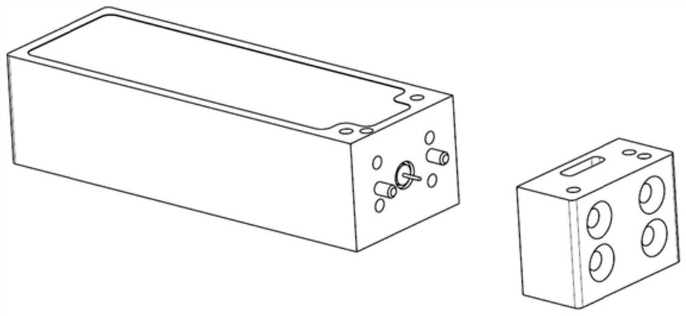
  • Figure 1
    Figure 1
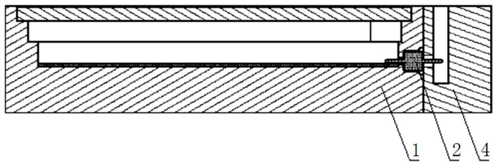
  • Figure 2
    Figure 2
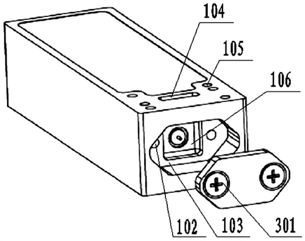
  • Figure 3
    Figure 3
Patent Text Reader

Abstract

The invention discloses an integrated waveguide-coaxial-microstrip transition structure which comprises a microwave box body, an insulator and a waveguide cover plate. A circuit groove is formed in the top surface of the microwave box body in a depth direction to install a microwave circuit, and the cover plate is arranged above the circuit groove; an end face groove is formed in one end face of the microwave box body, an end face waveguide cavity is formed in the end face groove, an external waveguide port is formed at the corresponding position above the end face waveguide cavity, namely the top face of the microwave box body, and waveguide mounting holes are formed in the two sides of the external waveguide port; the insulator is transversely arranged between the end face waveguide cavity and the circuit groove, one end of the insulator extends into the end face waveguide cavity, and the other end of the insulator is electrically connected with the microwave circuit in the circuit groove, and the waveguide cover plate is tightly matched with the end surface groove. According to the present invention, a main cavity is formed through one-time machining, and the waveguide cavity and the microwave box body are manufactured on one structural part, so that the machining and manufacturing are convenient and fast; the requirement for alignment between the waveguide cover plate and the microwave box body is low, and the performance deterioration caused by the matching precision problem of the waveguide cavity and the microwave box body is avoided.
Need to check novelty before this filing date? Find Prior Art

Description

technical field

[0001] The invention relates to the technical field of microwave circuits, in particular to a waveguide coaxial microstrip conversion circuit for microwave signals. Background technique

[0002] High-gain antennas usually choose the structure of the waveguide interface, such as horn antennas, waveguide slot arrays, etc. In applications that require high power capacity and insertion loss, rectangular waveguide connections are usually used between the antenna and the transmitter and receiver. And the microwave solid-state transmitter and receiver that comprise MMIC (Monolithic Microwave Integrated Circuit, monolithic microwave integrated circuit) chip usually adopt the mode of microstrip transmission to carry out integration, therefore need a kind of conversion circuit of rectangular waveguide to microstrip.

[0003] There are many forms of conversion between rectangular waveguide and microstrip line, the common forms are: waveguide-microstrip probe transition,...

Examples

Embodiment 1

[0042] Such as image 3 and 4As shown, this embodiment provides an integrated waveguide-coaxial-microstrip transition structure, including a microwave box body 1, an insulator 2, and a waveguide cover plate 3, wherein the top surface of the microwave box body 1 is provided with a circuit groove in the depth direction To install the microwave circuit, a cover plate 101 is arranged above the circuit slot. One end surface of the microwave box body 1 is provided with an end surface groove 103, and the waveguide cover plate 3 is closely matched with the end surface groove 103. An end face waveguide cavity 106 is arranged in the end face groove 103, an external waveguide port 104 is arranged on the corresponding position above the end face waveguide cavity 106, that is, the top surface of the microwave box body 1, and waveguide installation holes 105 are arranged on both sides of the external waveguide port 104. The insulator 2 is arranged laterally between the end face waveguide ...

Embodiment 2

[0056] This embodiment is on the basis of embodiment 1:

[0057] Such as Figure 5 As shown, the waveguide signal of the integrated waveguide-coaxial-microstrip transition structure is input from the top, the insulator 2 directly penetrates into the waveguide cavity 106 on the end face without passing through the air cylindrical cavity, and the waveguide signal is coupled and output by the conductor probe inside the insulator 2. This embodiment The size of the selected waveguide is 7.12mm×3.56mm. For the convenience of digital milling, the rounded corner of the waveguide is R0.5mm.

[0058] The diameter of the inner conductor of the insulator 2 is 0.3 mm, and the distance between the center and the bottom surface of the end face waveguide cavity 106 (waveguide short-circuit surface) is about a quarter of the wavelength of the center frequency, that is, 1.85 mm. About half of the side, the depth of the insulator 2 in this embodiment into the end face waveguide cavity 106 is 1....