
Cooperative damper for sports equipment and working method thereof

A technology for sports equipment and working methods, which is applied to sports accessories, gymnastics equipment, electric components, etc., can solve the problems of high power consumption, sports equipment cannot meet the use effect, and eddy current material has a large influence, and achieves high resistance precision. Effect

Pending Publication Date: 2021-08-24
厦门景杉网络科技有限公司
View PDF2 Cites 1 Cited by
  • Summary
  • Abstract
  • Description
  • Claims
  • Application Information

AI Technical Summary

Problems solved by technology

[0004] For the electromagnetic damping type, such as the electromagnetic resistance device disclosed in the patent document whose authorized announcement number is CN207843201U, it uses the principle of magnetic induction to place the rotating moving part in the magnetic field, and the moving part cuts the magnetic field to generate eddy current, and the interaction between the eddy current and the magnetic field generates Ampere force , so as to generate resistance. Although this method greatly improves the precision of the generated resistance, the generation of eddy current is greatly affected by the material, so the resistance precision is not high enough, and because an external current is required to generate resistance, more power consumption
[0005] As for the motor damping type, such as the damping motor disclosed in the patent document whose publication number is CN109011332A, it provides load torque through the motor, so that the coil rotates and cuts the magnetic field line to generate current, and generates Ampere force, thereby generating resistance. The damper of this structure produces The precision of the resistance is sufficient and the power consumption is smaller, but when the speed of the coil is low, the resistance generated by the coil cutting the magnetic force line is also relatively small, so that the sports equipment cannot meet the ideal use effect at low speed.

Method used


Image

  • Cooperative damper for sports equipment and working method thereof
  • Cooperative damper for sports equipment and working method thereof
  • Cooperative damper for sports equipment and working method thereof

Examples


Embodiment 1

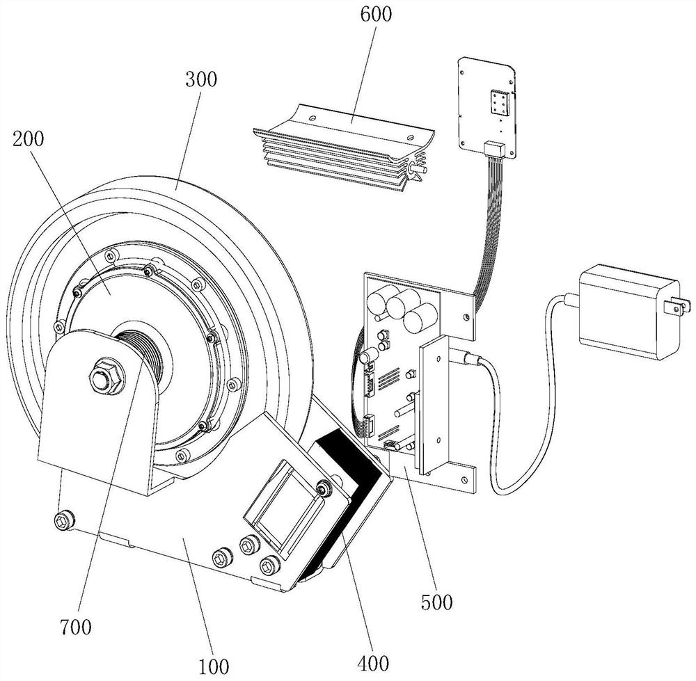
[0042] refer to figure 1 As shown, this embodiment discloses a cooperative damper for sports equipment, including a frame 100 , a damping motor 200 , a flywheel assembly 300 , an electromagnet assembly 400 , a controller 500 , a power resistor 600 and a transmission wheel 700 .

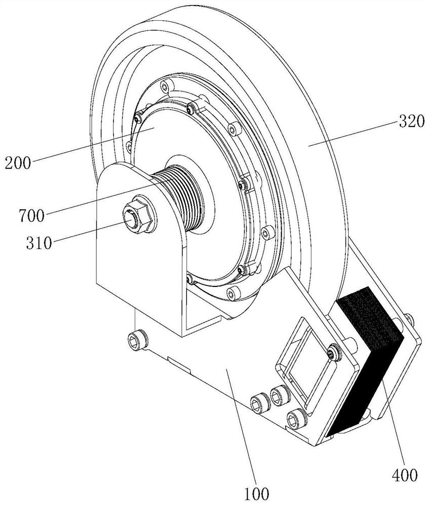
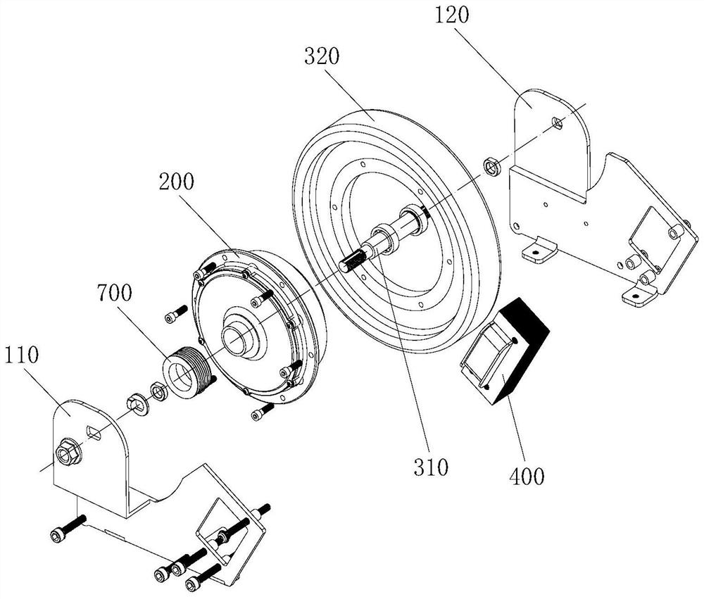
[0043] Cooperate Figure 1 to Figure 3 As shown, the flywheel assembly 300 includes a shaft 310 and a metal part 320 , the shaft 310 is installed on the frame 100 , the damper motor 200 is arranged on the shaft 310 , and the metal part 320 is fixed on the rotor of the damper motor 200 . The damping motor 200 is connected to the power resistor 600 through the controller 500 , and the phase current of the damping motor 200 is precisely controlled through the FOC control mode of the field oriented control, so as to realize the precise control of the resistance generated by the damping motor 200 . The transmission wheel 700 is installed on the rotor of the damping motor 200 , and the crankshaft 310 can b...

Embodiment 2

[0051] Cooperate figure 1 and Figure 6 As shown, this embodiment also discloses a working method of a cooperative damper for sports equipment, including the above-mentioned cooperative damper, and the specific working steps are as follows:

[0052] S1. Obtain the cadence data and the torque value required by the user acting on the flywheel assembly 300 within a preset period of time. In this embodiment, the torque value required by the user can be input by the user according to his own needs. It can also automatically match the torque value according to the user's situation.

[0053] S2. Comparing the acquired cadence data and the torque value required by the user with the cadence-torque threshold value of the damping motor 200, the controller 500 controls the damping motor 200 and the electromagnet assembly 400 to generate the flywheel assembly 300 according to the comparison result The magnitude of the resistance. In this embodiment, the controller 500 controls the genera...


PUM


Abstract

The invention discloses a cooperative damper for sports equipment. The cooperative damper comprises a rack, a damping motor, a flywheel assembly, an electromagnet assembly and a controller. The flywheel assembly comprises a crankshaft and a metal piece; the electromagnet assembly is located on one side of the metal piece. The controller is used for controlling the magnitude of current passing through the damping motor and the electromagnet assembly. The invention further discloses a working method of the sports equipment collaborative damper. The working method comprises the following steps: S1, acquiring the pedaling frequency data of a user acting on the flywheel assembly and a torque value needed by the user; S2, comparing the obtained pedaling frequency data and the torque value required by the user with a pedaling frequency-torque threshold value, and controlling the generated resistance according to the comparison result; S3, continuously acquiring the pedaling frequency data in the next preset time and the torque value required by the user, and comparing the pedaling frequency data with the torque value required by the user to provide accurate resistance for the flywheel assembly. When the rotating speed is low, the defect that the damping motor generates resistance can be overcome through the electromagnet assembly, the resistance is mainly provided through the motor, and therefore, higher resistance precision is provided, and more electricity is saved.

Description

technical field [0001] The invention relates to the technical field of sports equipment, and relates to a cooperative damper for sports equipment and a working method thereof. Background technique [0002] When sports equipment (such as fitness machines and trainers) is working, it needs to provide force loads through dampers. Currently, commonly used dampers generally include mechanical damping, electromagnetic damping, and motor damping. [0003] For the mechanical damping type, it generally generates resistance through friction with moving parts. The resistance generated by this method is uncontrollable, and it is gradually eliminated in many high-end sports equipment. [0004] For the electromagnetic damping type, such as the electromagnetic resistance device disclosed in the patent document whose authorized announcement number is CN207843201U, it uses the principle of magnetic induction to place the rotating moving part in the magnetic field, and the moving part cuts th...

Claims


Application Information

Patent Timeline
Patent Type & Authority Applications(China)
IPC IPC(8): H02K7/00H02K7/02H02K7/10F16F15/30F16F15/10A63B24/00A63B21/22A63B21/005
CPCA63B21/0052A63B21/0058A63B21/225A63B24/0087F16F15/10F16F15/30H02K7/003H02K7/025H02K7/10Y02E60/16
Inventor 李荣春
Owner 厦门景杉网络科技有限公司
Learn More