An Inner Helical Injection Vascular Robot Driven by External Magnetic Field

An internal spiral and external magnetic field technology, applied in the field of vascular robots, can solve the problems of slow progress, unstable movement process, and insufficient power of micro robots, and achieve the effect of improving flexibility, increasing movement speed, and realizing bidirectional movement.

Active Publication Date: 2022-03-22
GUANGZHOU UNIVERSITY
View PDF10 Cites 0 Cited by
  • Summary
  • Abstract
  • Description
  • Claims
  • Application Information

AI Technical Summary

Problems solved by technology

[0005] 2. By driving the elastic bellows shell to expand and contract axially, the micro-robot is driven to creep forward. This method makes the micro-robot move forward slowly, which is likely to cause insufficient power, and the movement process is very unstable, so it cannot drive the micro-robot to do continuous movement.

Method used


Image

  • An Inner Helical Injection Vascular Robot Driven by External Magnetic Field
  • An Inner Helical Injection Vascular Robot Driven by External Magnetic Field
  • An Inner Helical Injection Vascular Robot Driven by External Magnetic Field

Examples


Embodiment 1

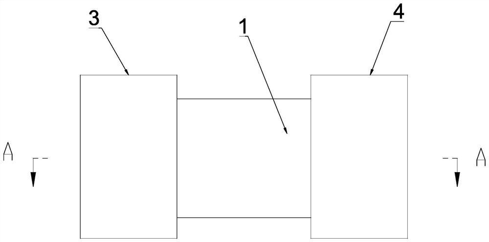
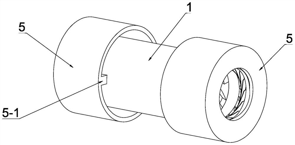
[0040] see Figure 1-Figure 4 , the present embodiment discloses an internal helical injection vascular robot driven by an external magnetic field, which includes a tube body 1, an annular permanent magnet 2 arranged on the tube body 1, and an annular permanent magnet 2 arranged at both ends of the tube body 1 for changing the tube body. A diameter-reducing device with openings at both ends of the body 1, and a spiral groove 1-1 is provided on the inner wall of the pipe body 1.

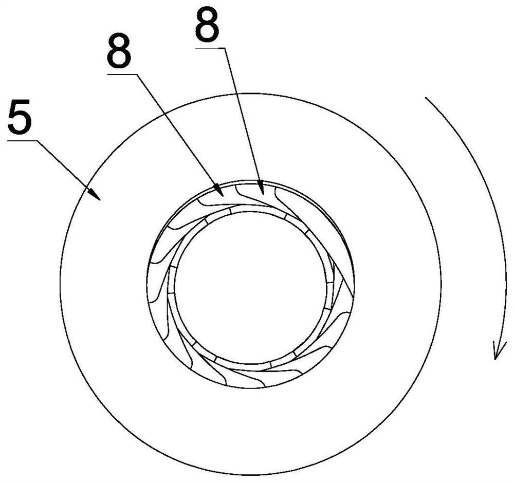
[0041] see Figure 1-Figure 6 , the diameter reducing device includes a left end diameter reducing device 3 located at the left end of the pipe body 1 and a right end diameter reducing device 4 located at the right end of the pipe body, the left end diameter reducing device 3 and the right end diameter reducing device 4 both include The connecting sleeve 5 at the end of the body 1, the fixed adjustment member 6 fixedly connected to the end of the pipe body 1 and arranged coaxially with the pipe body ...

Embodiment 2

[0061] see Figure 14 , the other structures in this embodiment are the same as in Embodiment 1, the difference is that the sliding adjustment groove 8-2 is an arc-shaped sliding adjustment groove, and the arc-shaped sliding adjustment groove is eccentrically arranged on the fixed adjustment member 6 , wherein, the rotation direction of the arc-shaped sliding adjustment groove in the left-end diameter reducing device 3 is opposite to the rotation direction of the arc-shaped sliding adjustment groove in the right-end diameter reducing device 4 . By setting the above-mentioned structure, the sliding adjustment groove 8-2 is arranged in an arc shape, and is eccentrically arranged on the fixed adjustment member 6, so that the stroke of the adjustment rod 8-4 in the sliding adjustment groove 8-2 can be improved, thereby improving the height of the adjustment blade. The swing angle of 8-1 can further increase the variation interval of the openings at both ends of the pipe body 1. By...


PUM


Abstract

The invention discloses an internal helical injection blood vessel robot driven by an external magnetic field, which includes a pipe body, an annular permanent magnet and a diameter reducing device. The inner wall of the pipe body is provided with a spiral groove; Diameter device, the left-end diameter-reducing device and the right-end diameter-reducing device both include connecting sleeves, fixed adjustment parts and installation positioning parts, multiple sets of caliber adjustment components are arranged between the fixed adjustment parts and the installation and positioning parts, and multiple sets of caliber adjustment components Arranged along the circumferential direction, each group of caliber adjustment components includes adjustment blades, sliding adjustment grooves, fixed rods and adjustment rods. The swing direction of the adjustment blades in the left end diameter reducing device is opposite to that in the right end diameter reduction device. The blood vessel robot can move forward and backward in the blood vessel, so as to realize two-way movement, and the movement mode is flexible, which is convenient for moving in the blood vessel. The movement process of the blood vessel robot is stable, the movement speed is fast, and it can continue to move in the blood vessel.

Description

technical field [0001] The invention relates to the technical field of blood vessel robots, in particular to an inner helical injection blood vessel robot driven by an external magnetic field. Background technique [0002] Vascular robot is a micro-robot that can enter blood vessels and move freely in blood vessels. It can complete tasks such as removing thrombus, resecting tumors, and administering drugs in blood vessels. It is of great significance to the prevention and treatment of cardiovascular and cerebrovascular diseases. Hotspots in the field of foreign micro-robot research. Researchers have conducted extensive research on vascular robots, involving the shape, movement mode, updating of manufacturing materials and upgrading of processing technology of vascular robots. [0003] Traditional vascular robots are generally divided into three types according to the movement mode, including swing type, spiral type and push type. The swing robot swings forward through the ...

Claims


Application Information

Patent Timeline
Patent Type & Authority Patents(China)
IPC IPC(8): A61B34/30A61B34/00
CPCA61B34/30A61B34/73A61B2034/303
Inventor 江帆江志超祝韬欧阳定雄
Owner GUANGZHOU UNIVERSITY
Why Eureka
Try Eureka