Pipe clamping and feeding device

A technology of feeding device and pipe fitting clamp, applied in the direction of pipe shearing device, positioning device, shearing device, etc., can solve the problems of slow feeding speed, low feeding efficiency, unsuitable for large batch feeding, etc., to prevent rolling , The effect of increasing the feeding speed

Inactive Publication Date: 2018-05-01
四川精通机械科技有限公司
View PDF0 Cites 1 Cited by
  • Summary
  • Abstract
  • Description
  • Claims
  • Application Information

AI Technical Summary

Problems solved by technology

Steel pipes are generally long in length, and sometimes it is necessary to cut a section for other purposes. The general method is to send the steel pipe to the cutting machine through the feeding device first, and clamp and cut it by cutting; but the existing feeding The device adopts roller feeding or manual feeding. When using roller feeding, the steel pipe is easy to roll on the roller, so that the steel pipe cannot be quickly clamped and loaded in the later clamping process; and manual feeding requires a lot of consumption labor force
The above two feeding methods are not only low in feeding efficiency, but also slow in feeding speed, which is not suitable for mass feeding

Method used


Image

  • Pipe clamping and feeding device
  • Pipe clamping and feeding device

Examples


Embodiment Construction

[0014] The present invention will be described in further detail below through specific implementation examples and in conjunction with the accompanying drawings.

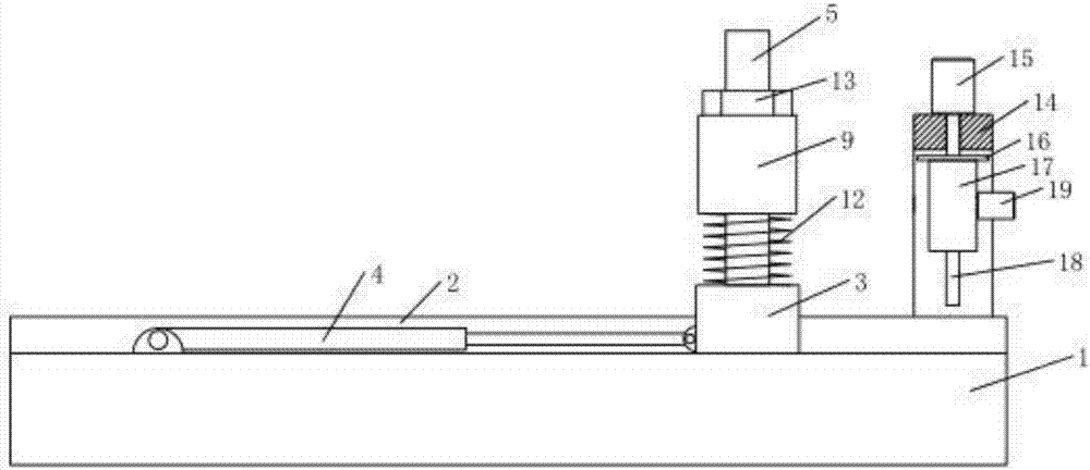
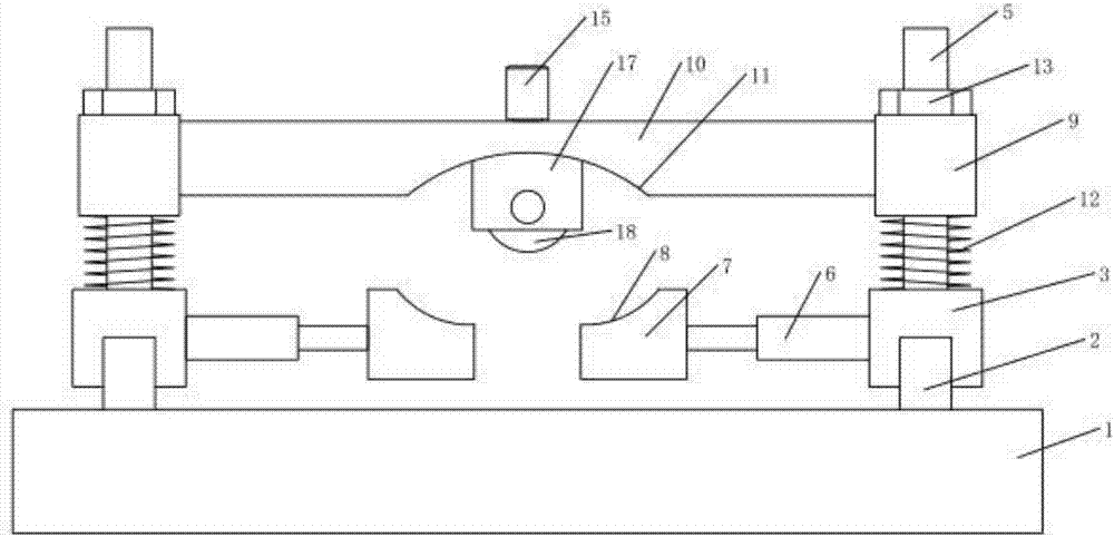
[0015] figure 1 , figure 2 Shown is a pipe fitting clamping and feeding device provided by the present invention, which includes a workbench 1 and two slide rails 2 arranged along the length direction of the workbench 1. The length of the slide rails 2 is consistent with the length of the workbench 1; The above two slide rails 2 are provided with a sliding slider 3, and the bottom of the slider 3 is provided with a chute that matches the slide rail 2, so that the slider 3 can slide smoothly on the slide rail 2, and the workbench 1 is hingedly provided with a first telescopic cylinder 4 that drives the slider 3 to slide, specifically, the first telescopic cylinder 4 is hingedly installed at the rear end, so that when the first telescopic cylinder 4 is stretched, it can push the slider 3 in the Advance on the guid...


PUM


Abstract

The invention discloses a pipe clamping and feeding device, and relates to the technical field of steel pipe machining equipment. The pipe clamping and feeding device comprises a worktable, and two sliding rails arranged in the length direction of the worktable. Sliding blocks capable of sliding are arranged on the two sliding rails. The worktable is hinged to a first telescopic air cylinder for driving the sliding blocks to slide. The two sliding blocks are both provided with vertical screw rods. Second telescopic air cylinders are fixedly arranged on the opposite surfaces of the two slidingblocks. Lower fixing blocks are fixedly arranged on piston rods of the second telescopic air cylinders and are both provided with lower pressing surfaces. The upper ends of the two screw rods are bothsleeved with movable sleeves, and an upper fixing block is connected between the two movable sleeves. The lower surface of the upper fixing block is provided with an upper pressing surface. The pipeclamping and feeding device can clamp and feed a steel pipe, effectively prevents the steel pipe from rolling in the feeding process, improves the feeding speed of the steel pipe, and is applicable tovolume production.

Description

technical field [0001] The invention relates to the technical field of steel pipe processing equipment, in particular to a clamping and feeding device for pipe fittings. Background technique [0002] Steel pipe is a hollow long strip of round steel, which is widely used in petroleum, chemical, medical, food, light industry, mechanical instrumentation and other industrial pipelines and mechanical structural components. In addition, when the bending and torsional strength are the same, the weight is lighter, so it is also widely used in the manufacture of mechanical parts and engineering structures. Steel pipes are generally long in length, and sometimes it is necessary to cut a section for other purposes. The general method is to send the steel pipe to the cutting machine through the feeding device first, and clamp and cut it by cutting; but the existing feeding The device adopts roller feeding or manual feeding. When using roller feeding, the steel pipe is easy to roll on t...

Claims


Application Information

Patent Timeline
Patent Type & Authority Applications(China)
IPC IPC(8): B23D33/02B23D21/00B23Q3/08B23Q7/06
CPCB23D33/02B23D21/00B23Q3/08B23Q7/06
Inventor 李和军
Owner 四川精通机械科技有限公司
Why Eureka
Try Eureka