
Numerical control profile end surface milling center

A face milling and machining center technology, applied in metal processing, metal processing equipment, metal processing machinery parts, etc., can solve the problems of high labor intensity, unstable cutting accuracy, low work efficiency, etc.

Pending Publication Date: 2021-08-27
JINAN CGMA CNC MACHINERY CO LTD
View PDF6 Cites 4 Cited by
  • Summary
  • Abstract
  • Description
  • Claims
  • Application Information

AI Technical Summary

Problems solved by technology

High degree of manual participation, high labor intensity, low work efficiency, and unstable cutting accuracy

Method used


Image

  • Numerical control profile end surface milling center
  • Numerical control profile end surface milling center
  • Numerical control profile end surface milling center

Examples


Embodiment 1

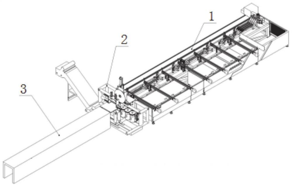
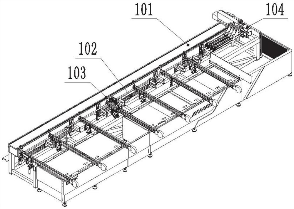
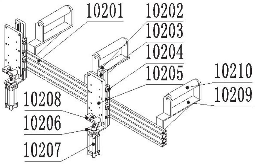
[0043] This embodiment provides a CNC profile end face milling machining center, which is suitable for profile processing, such as end face processing of aluminum alloy door and window profiles, such as figure 1 As shown, it includes a feeding section 1, a sawing section 2 and a discharging section 3 arranged in sequence, wherein the feeding section 1 includes a feeding frame 101, a lifting mechanism 102, a transmission mechanism 103, and a feeding claw mechanism 104. Through the feeding claw mechanism 104 realizes accurate feeding. The sawing section 2 includes a sawing frame 201 , a sawing part 202 , a milling part 203 , a pressing part 204 and a cutter 205 , and automatic cutting is realized through the sawing section 2 . In this embodiment, the moving direction of the profile along the feeding section 1 , the sawing section 2 and the discharging section 3 is taken as the X direction, and the transmission direction of the transmission mechanism 103 is taken as the Y directi...


PUM


Abstract

The invention discloses a numerical control profile end surface milling center, comprising a feeding section, a sawing section and a discharging section. The feeding section comprises a feeding frame; a conveying mechanism is installed in the feeding frame; a plurality of supporting mechanisms are arranged on one side of the conveying mechanism at intervals; a feeding claw mechanism is slidably connected to the inner wall of the feeding frame; the conveying mechanism is used for conveying a profile to the position above the supporting mechanism; the feeding claw mechanism is used for clamping the profile and is matched with the supporting mechanism to convey the profile to the sawing section; the sawing section comprises a sawing frame; a sawing part and a pressing part are sequentially mounted on the sawing frame; and the sawing part is used for cutting the profile pressed by the pressing part; the milling part is installed below the sawing part; and under the action of the feeding claw mechanism, the milling part can machine an end surface formed by sawing the profile; and the discharging section is used for outputting the profile processed by the milling part. According to the invention, automatic feeding can be achieved, a plurality of profiles can be machined at a time, double surfaces can be machined at a time, the profiles do not need to be manually turned around, and the profile machining efficiency is improved.

Description

technical field [0001] The invention relates to the field of profile processing, in particular to a numerically controlled profile end face milling machining center. Background technique [0002] The machine tool industry is the basic industry of the manufacturing industry, and numerical control equipment is the core product of the machine tool industry. With the intensive and standardized development of door and window processing enterprises, more and more large and medium-sized door and window processing enterprises at home and abroad need stable, reliable and suitable for the use of the door and window industry. A production line with a high degree of automation, and CNC face milling is the most critical step, which determines the efficiency and precision of door and window processing, and ultimately determines the overall quality of doors and windows. [0003] The common door and window end face milling machines on the market are generally cut off by cutting equipment, a...

Claims


Application Information

Patent Timeline
Patent Type & Authority Applications(China)
IPC IPC(8): B23P23/02B23Q7/00B23Q7/04B23Q3/00
CPCB23P23/02B23Q7/00B23Q7/04B23Q3/00B23Q2703/04
Inventor 宋远杰高振华
Owner JINAN CGMA CNC MACHINERY CO LTD
Learn More