
Roving core-spun yarn manufacturing device

A core-spun yarn and roving technology, applied in the field of roving frame, can solve the problems of incapable of discharging sewage, inconvenient recycling, reducing the effect of batt and dust settlement, etc., and achieve the effect of improving the settlement effect and avoiding the cost.

Active Publication Date: 2021-08-27
南通第十二棉纺织有限公司
View PDF4 Cites 0 Cited by
  • Summary
  • Abstract
  • Description
  • Claims
  • Application Information

AI Technical Summary

Problems solved by technology

[0004] However, during the use of the above-mentioned invention, the cotton wool and dust particles cannot be separated well, and it is not convenient to recycle the cotton wool in the later stage. At the same time, due to the characteristics of the cotton wool, the cotton wool can easily absorb the sewage produced. The absorbed sewage is well discharged, and further, it brings inconvenience to the later stage of recycling, and the nozzle of the above-mentioned invention is a fixed design, which cannot make the water sprayed by the nozzle diffuse well, and reduces the settlement effect of cotton wool and dust

Method used


Image

  • Roving core-spun yarn manufacturing device
  • Roving core-spun yarn manufacturing device
  • Roving core-spun yarn manufacturing device

Examples


Embodiment 1

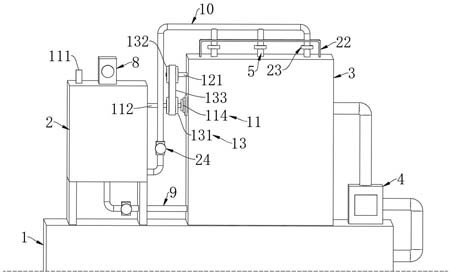
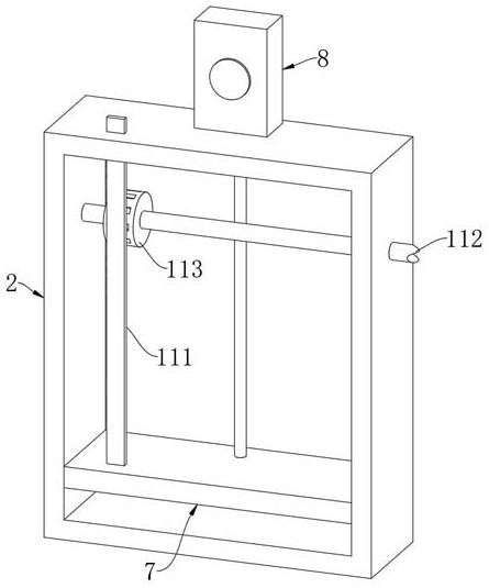
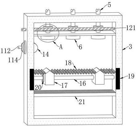
[0028] Such as Figure 1-5 As shown, a device for manufacturing roving core-spun yarn includes a roving frame main body 1, a water guide box 2, a dust removal box 3 and a dust collector 4 are fixedly connected to the roving frame main body 1, and the dust suction end of the dust collector 4 is connected to the roving The machine main body 1 is connected, and the output end of the dust collector 4 is connected with the dust removal box 3, and a plurality of drainage pipes 5 are connected in rotation in the dust removal box 3, and the lower end of the drainage pipe 5 is connected with a nozzle 6, and the setting of the nozzle 6 can make the water flow Better spraying, the piston plate 7 is slidably connected in the water guide box 2, and the upper end of the water guide box 2 is fixedly connected with the cylinder 8, the output end of the cylinder 8 is fixedly connected with the piston plate 7, and the cooperation of the cylinder 8 and the piston plate 7 can Regulate the air pre...

Embodiment 2

[0037] for Figure 6 The second embodiment shown is different from the first embodiment in that the filter screen 21 is sealed and slidably arranged in the dust removal box 3, and two support plates 25 are fixedly connected in the dust removal box 3, and there is a gap between the support plate 25 and the filter screen 21. A plurality of return springs 26 are fixedly connected, and a plurality of arc surfaces are arranged at intervals on the filter screen 21. The lower end of the slide plate 17 is fixedly connected with a connecting block 27, and the connecting block 27 is rotatably connected with a roller 28, and the roller 28 is in contact with the filter screen 21. Connection, through the cooperation of the provided roller 28 and the arc surface on the filter screen 21, the roller 28 can reciprocate and squeeze the filter screen 21 in the process of sliding with the slide plate 17, and at the same time, under the action of the return spring 26, the filter screen 21 can reci...


PUM


Abstract

The invention belongs to the field of roving frames, and particularly relates to a roving core-spun yarn manufacturing device. The roving core-spun yarn manufacturing device comprises a roving frame main body; a water guide box, a dust removal box and a dust suction machine are fixedly connected to the roving frame main body; the dust suction end of the dust suction machine communicates with the roving frame main body, and the output end of the dust suction machine communicates with the dust removal box; a plurality of drainage pipes are rotationally connected into the dust removal box; the water guide box communicates with the dust removal box through a water inlet pipe; the water guide box communicates with all the drainage pipes through a multi-head pipe; and a transmission mechanism is arranged between the water guide box and the dust removal box. Cotton fibers and dust particles generated in the working process of the roving frame main body are collected and settled, meanwhile, sewage absorbed by the cotton fibers can be removed, the cotton fibers can be well separated from the dust particles attached to the cotton fibers, the cotton fibers can be better recycled in the later period, and the time for cleaning the cotton fibers in the later period is saved.

Description

technical field [0001] The invention belongs to the field of roving frames, in particular to a device for manufacturing roving core-spun yarns. Background technique [0002] Nowadays, during the manufacturing process of core-spun yarn, it is often necessary to directly draw the cooked sliver into fine sand through the spinning frame, but the maximum drafting capacity of the spinning frame is 50 times, so a roving process is required between the drawing process and the spinning process To bear part of the drafting burden in spinning, therefore, in the manufacturing process of the core-spun yarn, it is necessary to use a roving frame to make roving first, and then pull out the spun yarn through the spinning frame. A dust removal device is often installed on the roving frame to process the roving frame Cotton and dust generated during work. [0003] The existing patent (notification number: CN209759673U) is a cotton suction and dust removal device used in the core-spun roving ...

Claims


Application Information

Patent Timeline
IPC IPC(8): D01H11/00B01D47/08B01D33/03B01D33/42
CPCB01D33/03B01D33/0346B01D33/42B01D47/08B01D2247/04D01H11/005
Inventor 季学宁
Owner 南通第十二棉纺织有限公司
Learn More