Method for synchronously determining boundary electric field and current density of diode

A current density and diode technology, applied in the field of vacuum electronic devices, can solve problems that cannot be solved and are not given, and achieve the effect of solving nonlinear and double boundary problems

Active Publication Date: 2021-08-27
SOUTH CHINA UNIV OF TECH
View PDF5 Cites 1 Cited by
  • Summary
  • Abstract
  • Description
  • Claims
  • Application Information

AI Technical Summary

Problems solved by technology

The method proposed in this technical document has some shortcomings. First, this method is only suitable for solving the case where the boundary electric field is zero. For more general cases, this technical document does not give a specific method; second: this method only Involving a single boundary problem, when there are two kinds of charges in the diode, that is, a double boundary problem, the method proposed in this technical document cannot solve it

Method used


Image

  • Method for synchronously determining boundary electric field and current density of diode
  • Method for synchronously determining boundary electric field and current density of diode
  • Method for synchronously determining boundary electric field and current density of diode

Examples


Embodiment 1

[0045] Embodiment 1: In the case where both electron and ion currents are non-uniform under the limited emission area, the method for synchronously determining the boundary electric field and current density of the diode comprises the following steps:

[0046] Step 1. Initial parameter setting

[0047] Given two different vectors of initial value of electron current density and one vector of initial value of ion current density;

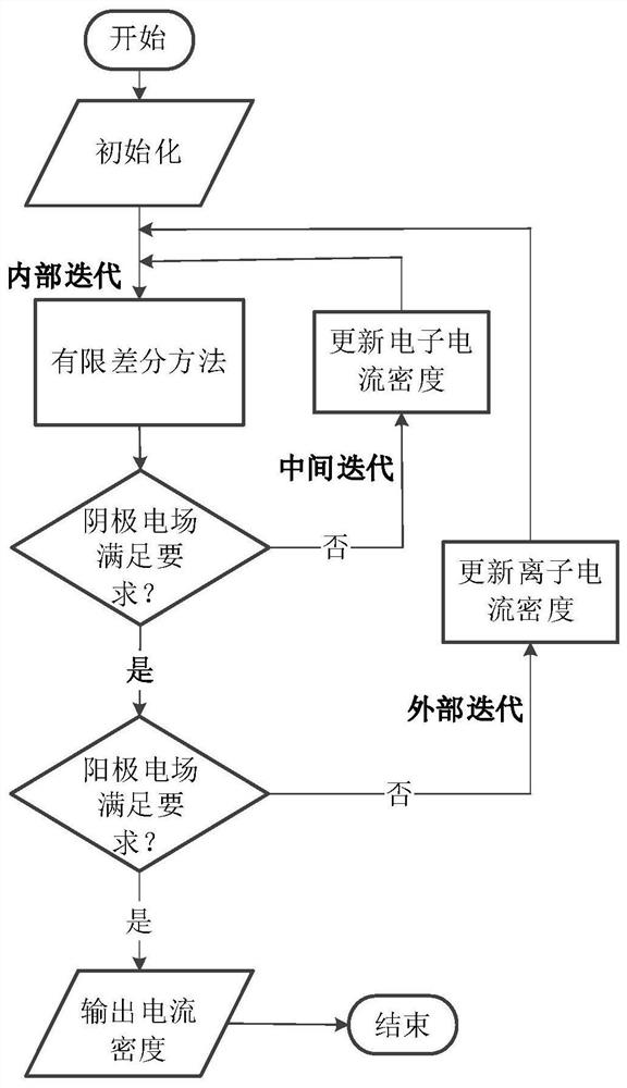
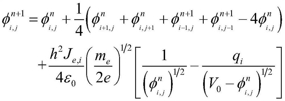
[0048] Step 2. Internal iteration

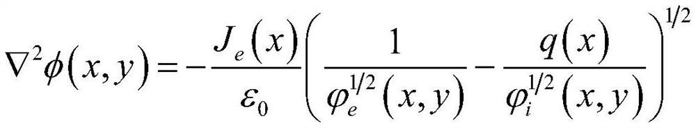
[0049] If the cathode potential of a given diode is zero and the anode potential is V 0 , the charge emission region is located at the center of the boundary, the width is W, and the injected electron current density at the cathode x is J e (x), the implanted ion current density at the anode x is J i (x), the potential at space (x, y) is φ(x, y), then the Poisson equation under the limited emission area can be expressed as:

[0050]

[0051] for|x|≤W / 2

[0052] In the formula, ε 0 、m i , Z, m e , x, y ...

Embodiment 2

[0074] Embodiment 2: In the case where the electron current is non-uniform but the ion current is uniform under the limited emission area, the method for synchronously determining the boundary electric field and current density of the diode comprises the following steps:

[0075] Step 1. Initial parameter setting

[0076] Given two different initial value vectors of electron current density and one initial value vector of ion current density, since the ion current is uniformly distributed, in the emission region, the ion current density is equal to a fixed constant;

[0077] Step 2. Internal iteration

[0078] If the cathode potential of a given diode is zero and the anode potential is V 0 , the charge emission region is located at the center of the boundary, the width is W, and the injected electron current density at the cathode x is J e (x), the implanted ion current density at the anode x is J i (x), the potential at space (x, y) is φ(x, y), then the Poisson equation un...

Embodiment 3

[0102] Embodiment 3: In the case where the electron and ion currents are uniform under the limited emission area, the method for synchronously determining the boundary electric field and current density of the diode comprises the following steps:

[0103] Step 1. Initial parameter setting

[0104] Given two different initial value vectors of electron current density and one initial value vector of ion current density, since the electron and ion currents are uniformly distributed, in the emission region, the electron and ion current densities are both equal to a fixed constant;

[0105] Step 2. Internal iteration

[0106] If the cathode potential of a given diode is zero and the anode potential is V 0 , the charge emission region is located at the center of the boundary, the width is W, and the injected electron current density at the cathode x is J e (x), the implanted ion current density at the anode x is J i (x), the potential at space (x, y) is φ(x, y), then the Poisson ...


PUM


Abstract

The invention discloses a method for synchronously determining a boundary electric field and current density of a diode. The method comprises the following steps: 1, giving two electron current density initial values and an ion current density initial value; 2, substituting the initial value of the electron current density and the initial value of the ion current density into a Poisson equation to obtain a corresponding cathode boundary electric field value; 3, predicting an electron current density value; 4, obtaining a new cathode boundary electric field value based on the predicted electron current density value, and judging whether the new cathode boundary electric field value meets the required cathode boundary condition or not; 5, giving a new ion current density value, and executing the step 1 to the step 4 to obtain two anode boundary electric field values; 6, predicting an ionic current density value; 7, predicting an anode boundary electric field value, and judging whether the predicted anode boundary electric field value meets the required anode boundary condition or not; and 8, outputting the final electron and ion current density.

Description

technical field [0001] The invention relates to the field of vacuum electronic devices, in particular to a method for synchronously determining the boundary electric field and current density of a diode. Background technique [0002] In order to meet the increasing energy demand and reduce the dependence on traditional energy sources, the development of high-performance thermoelectric conversion technology has attracted great attention from all over the world. A thermionic energy converter is a vacuum diode device that converts thermal energy directly into electrical energy. However, when solving the maximum current density allowed to flow through the device, it is difficult to solve the nonlinear problem analytically, especially after the introduction of ions, because both the electron and ion current densities are unknown, and whether with the increase of the electron and ion current density, Whether the cathode and anode can meet the required boundary conditions is also ...

Claims


Application Information

Patent Timeline
Patent Type & Authority Applications(China)
IPC IPC(8): G06F30/20G06F17/11G06F17/15
CPCG06F30/20G06F17/11G06F17/15
Inventor 朱映彬廖美焱姚若河耿魁伟
Owner SOUTH CHINA UNIV OF TECH
Why Eureka
Try Eureka