
Reactor pressure vessel main pipeline nozzle internal inspection equipment

A technology for pressure vessels and main pipes, which is applied in the field of internal inspection equipment for reactor pressure vessel main pipe nozzles, can solve problems such as inability to accurately control cameras, inaccurate inspection results, safety accidents in nuclear power plants, etc., to achieve less nuclear island resources, The effect of saving the overhaul period and avoiding safety accidents

Pending Publication Date: 2021-08-27
CGNPC INSPECTION TECH +3
View PDF8 Cites 0 Cited by
  • Summary
  • Abstract
  • Description
  • Claims
  • Application Information

AI Technical Summary

Problems solved by technology

In order to determine the quality of nuclear reactor pressure vessels, the inspection specifications and programs of nuclear power plants and nuclear power plants put forward mandatory requirements for non-destructive testing of welds and other parts of pressure vessels, and specify that they should be inspected before putting into operation and during operation. Carry out pre-service and in-service inspections of pressure vessels after a certain time interval; at present, the inspection of the intersection area between the nozzle of the main pipe of the reactor pressure vessel and the nozzle of the pressure vessel is mainly performed by tying the camera to a long pole, and then manual operation The rod body drives the camera to inspect the inside of the nozzle. This method is not only very inconvenient to operate, but also very inefficient. Moreover, because the position of the camera cannot be precisely controlled, the inspection results are not accurate enough, which may easily lead to safety accidents in nuclear power plants.

Method used


Image

  • Reactor pressure vessel main pipeline nozzle internal inspection equipment
  • Reactor pressure vessel main pipeline nozzle internal inspection equipment
  • Reactor pressure vessel main pipeline nozzle internal inspection equipment

Examples


Embodiment Construction

[0023] The present invention will be described in further detail below in conjunction with the accompanying drawings and specific embodiments.

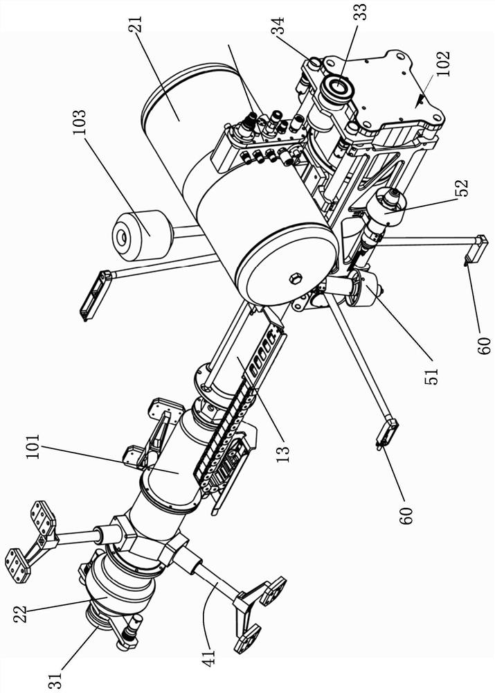
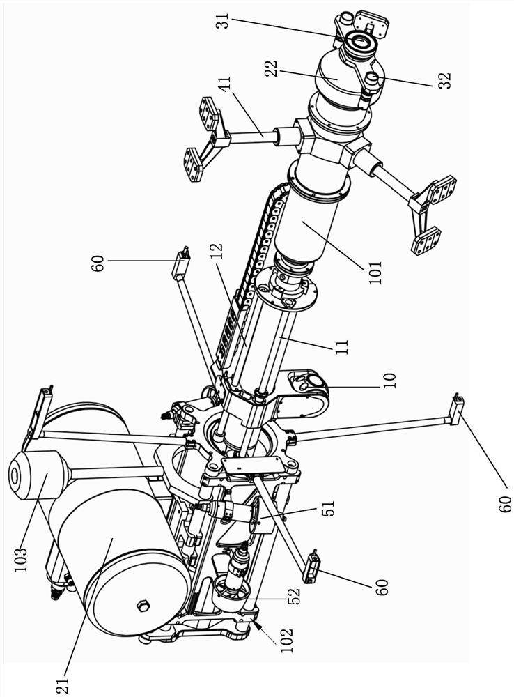
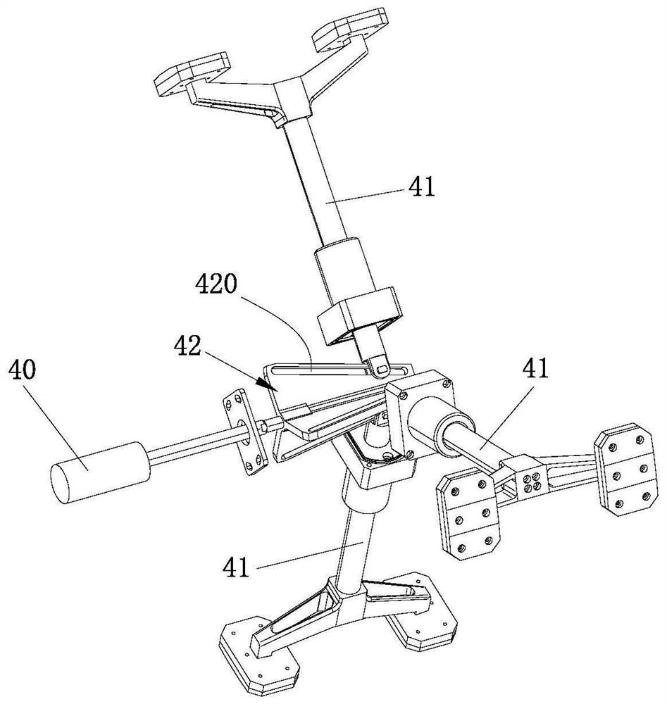
[0024] Such as Figure 1 to Figure 5 As shown, an internal inspection device for the main pipe nozzle of a reactor pressure vessel. The inspection device includes a diving inspection mechanism, a positioning mechanism, and a control module for controlling the action of the diving inspection mechanism and the positioning mechanism. The diving inspection mechanism includes a frame for inspecting the nozzle. The inspection module for internal defects, the buoyancy module for providing buoyancy, the power module for providing underwater movement power, the search module for exploring the underwater environment, and the positioning mechanism includes a position for inductive detection of the location of the diving inspection mechanism The detection component and the fixing component for fixing the position of the diving inspection mechanis...


PUM


Abstract

The invention relates to reactor pressure vessel main pipeline nozzle internal inspection equipment which comprises a diving inspection mechanism, a positioning mechanism and a control module for controlling the diving inspection mechanism and the positioning mechanism to act. The diving inspection mechanism comprises a rack, an inspection module used for inspecting internal defects of a pipe nozzle, a buoyancy module used for providing buoyancy, a power module used for providing diving motion power and a searchlighting module used for searchlighting the underwater environment. The positioning mechanism comprises a position detection assembly for sensing and detecting the position of the diving inspection mechanism and a fixing assembly for fixing the position of the diving inspection mechanism; according to the internal inspection equipment for the main pipeline nozzle of the reactor pressure vessel, the overhaul period is shortened, and few nuclear island resources are occupied; and the equipment can accurately position an inspection area, the positioning precision is 0.1 mm, the inspection efficiency is high, the inspection accuracy is high, and reactor safety accidents are avoided.

Description

technical field [0001] The invention relates to a device for inspecting the inside of a nozzle of a main pipe of a reactor pressure vessel. Background technique [0002] The nuclear reactor pressure vessel is one of the most important components of a nuclear power plant. It is used to fix, support and contain the core and all reactor internals. It is the only large-scale component that cannot be replaced during the entire life of the nuclear power plant. The quality of the nuclear reactor pressure vessel is the key to ensure the normal and safe operation of the nuclear power system. In order to determine the quality of nuclear reactor pressure vessels, the inspection specifications and programs of nuclear power plants and nuclear power plants put forward mandatory requirements for non-destructive testing of welds and other parts of pressure vessels, and specify that they should be inspected before putting into operation and during operation. Carry out pre-service and in-ser...

Claims


Application Information

Patent Timeline
IPC IPC(8): G21C17/017G21C17/003
CPCG21C17/017G21C17/003Y02E30/30
Inventor 严志刚王彬刘步良王海军刘军石磊
Owner CGNPC INSPECTION TECH
Learn More