Double-sided grinding machine tool

A technology of grinding mechanism and machine tool, which is applied in the direction of grinding machine, grinding machine parts, grinding frame, etc., can solve the problems of low grinding precision of brake pads and so on.

Active Publication Date: 2021-08-31
周吉
View PDF8 Cites 8 Cited by
  • Summary
  • Abstract
  • Description
  • Claims
  • Application Information

AI Technical Summary

Problems solved by technology

[0006] In view of the above problems, the present invention provides a double-sided grinding machine tool, which can slide along the radial direction of the brake pad by arranging the upper grinding sheet and the lower grinding sheet on the upper and lower end faces of the brake pad to be able to slide along the radial direction of the brake pad, and cooperate with the

Method used


Image

  • Double-sided grinding machine tool
  • Double-sided grinding machine tool
  • Double-sided grinding machine tool

Examples


Embodiment

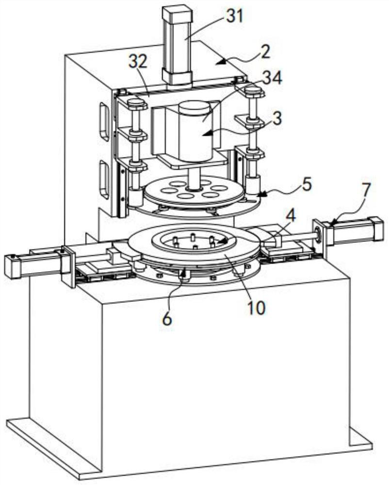
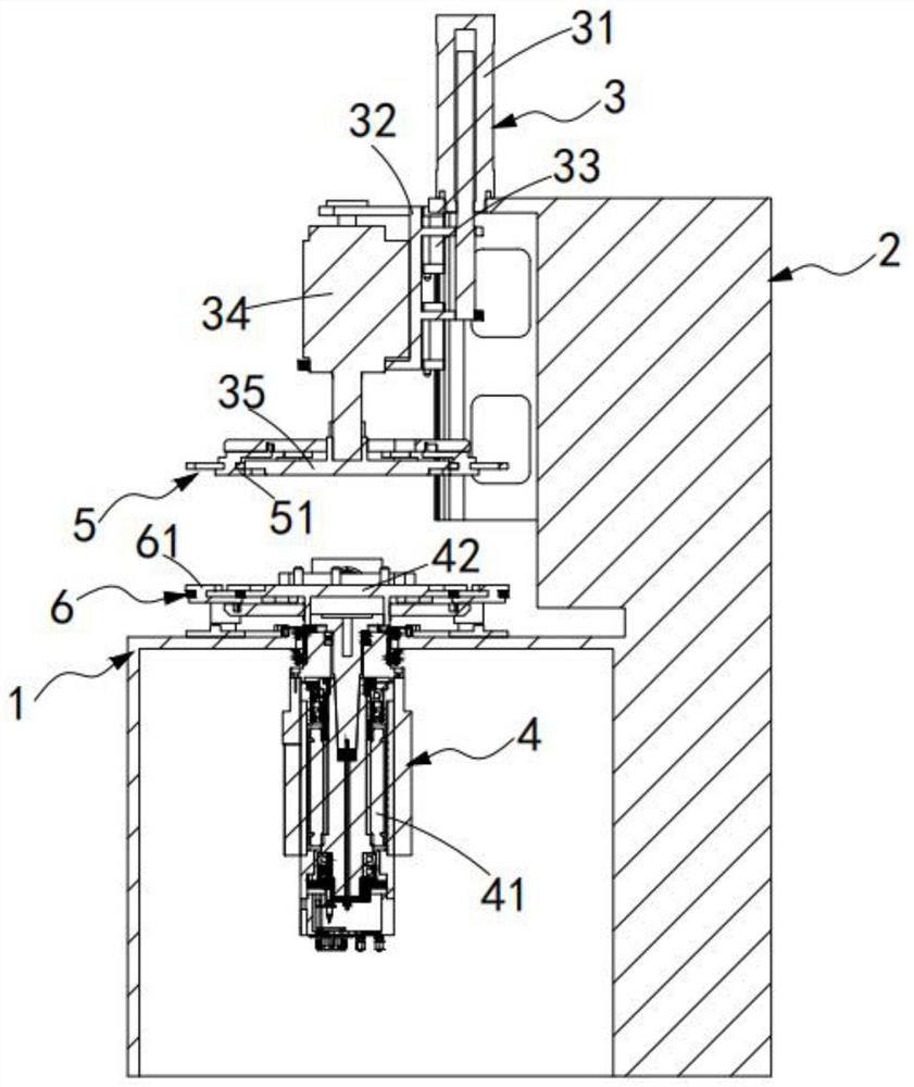
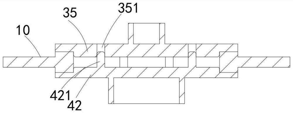
[0061] Such as Figures 1 to 3 As shown, a double-sided grinding machine tool includes a processing table 1 and an installation column 2, and the installation column 2 is adjacent to the processing table 1, and also includes:

[0062] A hydraulic mechanism 3, the hydraulic mechanism 3 is installed on the top of the installation column 2, the hydraulic mechanism 3 is located directly above the processing table 1, and the hydraulic mechanism 3 is used to press and position the processing table 1 to be Polished brake pads 10;

[0063] A loading mechanism 4, the loading mechanism 4 is installed on the processing table 1, the loading mechanism 4 is used to carry the brake pad 10, and drive the brake pad 10 to rotate;

[0064] An upper grinding mechanism 5, the upper grinding mechanism 5 is installed directly above the processing table 1, the upper grinding mechanism 5 is driven and lifted by the hydraulic mechanism 3, and the upper grinding mechanism 5 includes The upper grinding...

Embodiment approach

[0096] Such as Figure 10 As shown, as a preferred embodiment, the side grinding mechanism 7 includes:

[0097] A side sliding seat 71, the side sliding seat 71 is installed on the processing table 1 through a slide rail group 72, and the slide rail group 72 is arranged towards the loading mechanism 4;

[0098] A side grinding blade 73, the side grinding blade 73 is installed on the side sliding seat 71, and the side grinding blade 73 is attached to and grinds the side wall of the brake pad 10; and

[0099]The side thrust cylinder 74 is installed on the processing table 1 , and the side thrust cylinder 74 pushes the side sliding seat 71 to be slidably arranged.

[0100] It should be noted that, in the process of grinding the upper and lower end faces of the brake pad 10 , the side wall of the brake pad 10 is simultaneously ground by the side grinding blade 73 .


PUM


Abstract

The invention relates to the technical field of brake disc double-sided grinding, in particular to a double-sided grinding machine tool, which comprises a machining table, a mounting stand column, a hydraulic mechanism, a carrying mechanism, an upper grinding mechanism, a lower grinding mechanism and a side grinding mechanism, wherein the upper grinding mechanism comprises an upper grinding piece arranged in the radial direction of a brake pad in a sliding mode; and the lower grinding mechanism comprises a lower grinding piece arranged in the radial direction of the brake pad in a sliding mode. The upper grinding piece and the lower grinding piece which are arranged on the upper end face and the lower end face of the brake pad and used for grinding can slide in the radial direction of the brake pad to be matched with rotation of the brake pad, and the upper grinding piece and the lower grinding piece move and grind on the grinding end face of the brake pad in an 8-shaped track on the brake pad, so that the grinding precision of the brake pad is improved, and the technical problem that an existing double-sided grinding machine tool is low in grinding precision of the brake pad is solved.

Description

technical field [0001] The invention relates to the technical field of double-sided grinding of brake discs, in particular to a double-sided grinding machine tool. Background technique [0002] The brake disc is a round brake disc. When the car is moving, it also rotates. The brake caliper clamps the brake disc to generate braking force. When the brake is stepped on, it clamps the brake disc to slow down or stop. Disc brakes provide better braking and are easier to maintain than drum brakes. [0003] After the brake disc is worn out, it is generally necessary to polish and repair the surface burrs. However, most traditional grinding devices can only be ground on one side after being clamped by the machine tool, and then reversed again after grinding for secondary grinding. The clamping stability is low, and the positioning is prone to deviation, which affects the processing and grinding effect of the brake disc. [0004] Patent No. CN202010509648.7 discloses a brake disc d...

Claims


Application Information

Patent Timeline
IPC IPC(8): B24B7/17B24B5/01B24B9/00B24B27/00B24B47/12B24B41/06B24B41/02B24B47/22B24B41/047B24D7/06
CPCB24B7/17B24B5/01B24B9/00B24B27/0076B24B47/12B24B41/06B24B41/02B24B47/22B24B41/047B24D7/06
Inventor 周吉陈兆强叶灵勇王伟中金超焕陈慧吕江微韩勇娜褚辉远单才华徐高杨
Owner 周吉
Why Eureka
Try Eureka