
Conductive fabric wrapping core penetrating machine and method

A technology of conductive cloth and core threading machine, which is applied in the field of conductive cloth wrapping core threading machine, can solve the problems of high labor intensity, low efficiency, and difficulty in maintaining consistent product quality, so as to improve processing efficiency, improve quality stability, and avoid artificial wrong effect

Pending Publication Date: 2021-08-31
DONGGUAN JPOND IND CO LTD
View PDF0 Cites 0 Cited by
  • Summary
  • Abstract
  • Description
  • Claims
  • Application Information

AI Technical Summary

Problems solved by technology

[0003] In the traditional technology, the conductive cloth is usually manually wrapped on the outside of the foam strip, but the labor intensity of manual wrapping is too high and the efficiency is low
In order to improve the wrapping efficiency, auxiliary wrapping jigs have appeared on the market. Workers manually operate the jigs to wrap the conductive cloth on the foam strips. However, the jigs cannot liberate people's hands, and workers still need to continue to participate in the operation to complete the processing. As a result, the processing efficiency of the conductive cloth foam strip is still relatively low, and the quality of the product is difficult to maintain.

Method used


Image

  • Conductive fabric wrapping core penetrating machine and method
  • Conductive fabric wrapping core penetrating machine and method
  • Conductive fabric wrapping core penetrating machine and method

Examples


Embodiment Construction

[0039] In order to facilitate understanding of the present invention, the present invention will be described more fully hereinafter with reference to the related drawings. The preferred embodiments of the invention are shown in the accompanying drawings. However, the present invention may be embodied in many different forms and is not limited to the embodiments described herein. Rather, these embodiments are provided so that a thorough and complete understanding of the present disclosure is provided.

[0040] It should be noted that when an element is referred to as being "fixed to" another element, it can be directly on the other element or intervening elements may also be present. When an element is referred to as being "connected" to another element, it can be directly connected to the other element or intervening elements may also be present. The terms "vertical", "horizontal", "left", "right" and similar expressions used herein are for the purpose of illustration only ...


PUM


Abstract

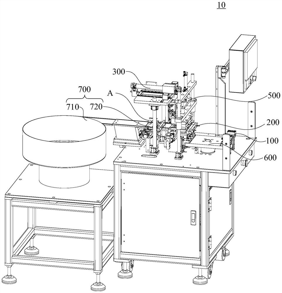
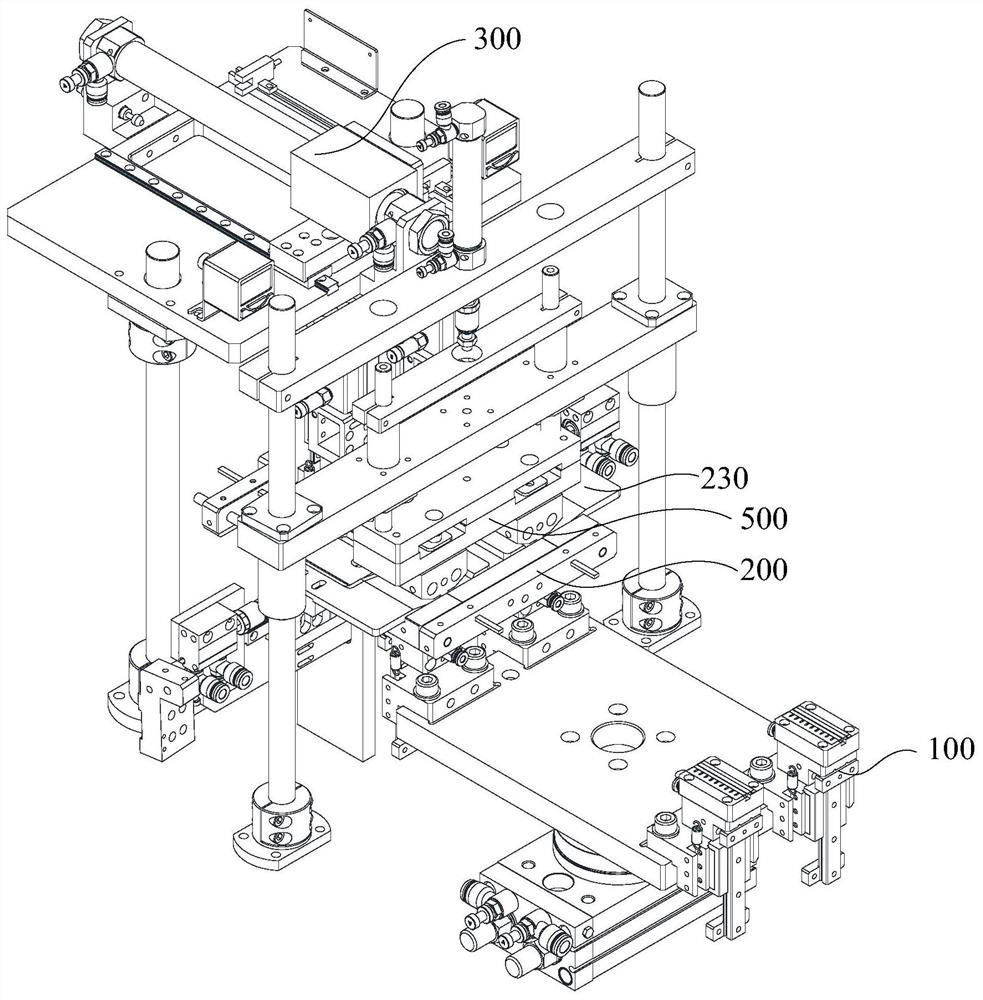
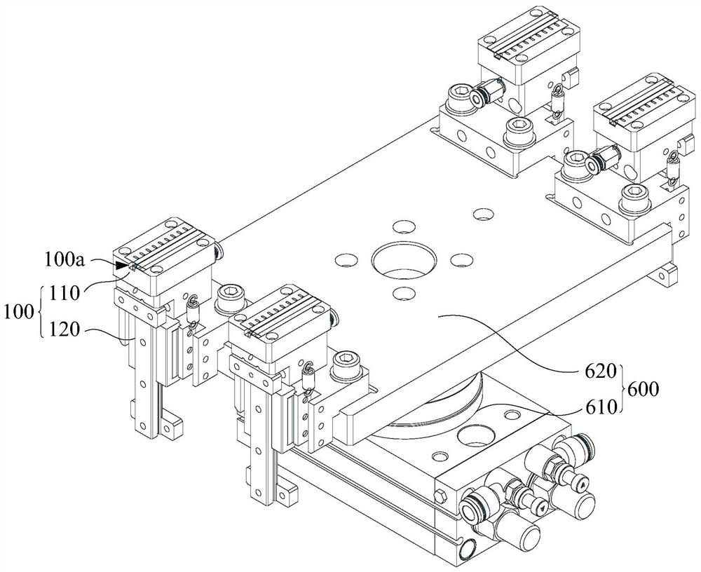
The invention provides a conductive fabric wrapping core penetrating machine and method. The conductive fabric wrapping core penetrating machine comprises a feeding mechanism, a core penetrating mechanism and a carrying mechanism, wherein a forming groove is formed in the feeding mechanism; the feeding mechanism is used for placing conductive fabric; the core penetrating mechanism comprises a core penetrating base, a forming assembly and a folding assembly; a foam hole, a connecting hole and a forming hole which are sequentially connected are formed in the core penetrating base; the forming end of the forming assembly is movably arranged in the connecting hole, the forming hole and the foam hole in a penetrating manner; the feeding mechanism is used for moving the conductive fabric into the forming hole to be formed; the power output end of the folding assembly is movably connected to the core penetrating base and used for pushing and folding two warped sides of the conductive fabric; the carrying mechanism is used for moving foam strips into the foam hole; and the forming end of the forming assembly is used for pushing the foam strips to enter the forming hole after passing through the connecting hole. The whole process of processing the foam strips of the conductive fabric is mechanically completed, continuous processing can be achieved, and the processing efficiency of the foam strips of the conductive fabric is improved.

Description

technical field [0001] The invention relates to the technical field of conductive cloth foam sliver processing, in particular to a conductive cloth wrapping core-piercing machine and a method thereof. Background technique [0002] The conductive cloth foam sliver is composed of conductive cloth wrapped with conductive foam. A hot melt adhesive is arranged between the conductive cloth and the conductive foam. The hot melt adhesive bonds the conductive cloth and the conductive foam into an integrated structure. On the outer side of the fuselage, there is a conductive glue for fixing the conductive cloth foam sliver. [0003] In the traditional technology, the conductive cloth is generally wrapped manually on the outside of the foam sliver, but the labor intensity of manual wrapping is too high and the efficiency is low. In order to improve the efficiency of wrapping, there are jigs for auxiliary wrapping on the market. Workers manually operate the jigs to wrap the conductive ...

Claims


Application Information

Patent Timeline
Patent Type & Authority Applications(China)
IPC IPC(8): B29C69/00B29C65/56B29C53/04
CPCB29C53/04B29C65/56B29C66/80B29C69/00
Inventor 胡宗维覃若峰陈聪赵强
Owner DONGGUAN JPOND IND CO LTD
Learn More