Angle-adjustable laser cutting device

A laser cutting and adjustable technology, which is applied in the direction of laser welding equipment, welding equipment, metal processing equipment, etc., can solve the problems of tool breakage, easily damaged cutter head, and barbs at the cutting edge, etc., and achieve the effect of increasing speed

Active Publication Date: 2021-04-06
深圳科锐尔精工技术有限公司
View PDF5 Cites 0 Cited by
  • Summary
  • Abstract
  • Description
  • Claims
  • Application Information

AI Technical Summary

Problems solved by technology

[0003] When cutting the pipe, use the cutting tool to position and rotate on the outer wall of the pipe. The rotating roller on the cutting machine drives the pipe itself to rotate, so as to cut the pipe wall of the pipe and cut the pipe into a suitable length and cutting opening. However, the pipe cutting When the rotating roller on the machine drives the pipe to rotate, because the outer wall of the pipe is arc-shaped, there is a certain gap between the rotating roller and the pipe, resulting in a certain vibration of the pipe during the rotation, which is different from the cutting tool. The friction between them is constantly increasing, which is likely to cause the cutter to break during the cutting process. At the same time, the cutting edge of the pipe that produces vibration is likely to have barbs, resulting in poor sealing when the pipe is spliced ​​after cutting. In summary, the existing The pipe cutting machine has the disadvantages that the cutting edge of the cut pipe is prone to barbs, and the temperature of the cutter rises sharply during the rotation process, which is easy to damage the cutter head, and the uneven incision is not conducive to splicing.

Method used


Image

  • Angle-adjustable laser cutting device
  • Angle-adjustable laser cutting device
  • Angle-adjustable laser cutting device

Examples


Embodiment 1

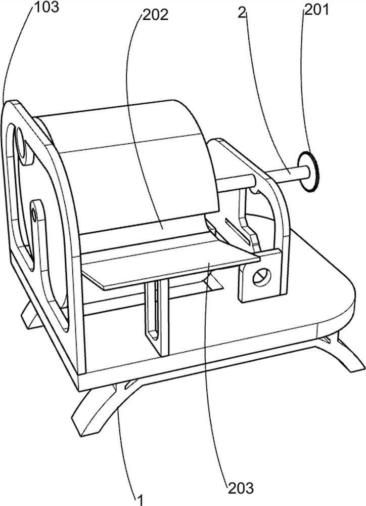
[0029] Such as Figure 1-2As shown, an angle-adjustable laser cutting device includes a base 1, a frame 101, a motor 1011, a missing gear 1012, a first bracket 102, a support plate 103, a bucket cover 104, a second bracket 105, and a third bracket 106, the fourth bracket 107, the intermittent rotation assembly, the cutting assembly and the limit assembly, the upper side of the base 1 is fixedly installed with the frame 101, the first bracket 102, the support plate 103, the second bracket 105, the third bracket 106 and the fourth bracket. Support 107, the frame 101 is located on the right side of the base 1, the support plate 103 is located on the left side of the base 1, the first support 102 is located on the right front side of the support plate 103, the second support 105 is located on the left side of the frame 101, and the second support 105 There is a straight chute 1051 in the middle part below, the third support 106 is positioned at the left side of the second support ...

Embodiment 2

[0032] Specific reference Figure 3-7 , on the basis of Embodiment 1, the intermittent rotating assembly includes a long rotating shaft 2, a first gear 201, a three-station drum 202 and a feeding swash plate 203, and the long rotating shaft 2 rotates through the center of the support plate 103, the bucket The upper middle part of the cover 104 and the second bracket 105, the right end of the long rotating shaft 2 is fixedly connected with the first gear 201, the first gear 201 meshes with the missing gear 1012, and the three-station drum 202 is fixedly connected with the left end of the long rotating shaft 2, three The station drum 202 is completely placed in the barrel cover 104 , the rear end of the feeding ramp 203 is fixedly connected to the lower side of the feeding port 1042 , and the feeding ramp 203 is fixedly connected to the upper side of the first bracket 102 .

[0033] The missing gear 1012 will mesh with the first gear 201 during rotation. At this time, the missin...

Embodiment 3

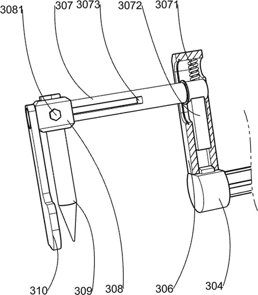
[0041] Specific reference Figure 8 On the basis of Embodiment 2, it also includes a toggle lever 5, a sliding plate 501, a bump 5011, a triangular block 502, a sliding column 503 and a fifth spring 504, and the toggle lever 5 is fixedly connected to the long rotating shaft 2 , the toggle lever 5 is between the second bracket 105 and the first gear 201, the sliding plate 501 slides through the straight chute 1051, the triangular block 502 is slidably connected with the base 1, the second bracket 105 and the third bracket 106, and the triangular The right side of the block 502 is fixedly connected to the left side of the sliding plate 501, the lower side of the bump 5011 is fixedly connected to the upper right side of the sliding plate 501, the bump 5011 touches the toggle lever 5, and the sliding column 503 slides through the second bracket 105 , the rear end of the sliding post 503 is fixedly connected to the front side of the triangular block 502, the fifth spring 504 is sle...


PUM


Abstract

The invention relates to pipeline production and processing equipment, in particular to an angle-adjustable laser cutting device. According to the angle-adjustable laser cutting device, a pipeline notch is smooth, a tool bit is not prone to being damaged, the notch cutting angle can be adjusted conveniently, and the angle-adjustable laser cutting device can adapt to pipelines of different types. The angle-adjustable laser cutting device comprises a base, a rack, a motor, a first support, a supporting plate and the like. The rack, the first support and the supporting plate are fixedly installed on the base; the rack and the supporting plate are located on the two sides of the base; and the motor is fixedly connected to the end, away from the base, of the rack. According to the angle-adjustable laser cutting device, pipeline cutting is completed through mutual cooperation of a first regulation and control assembly and a second regulation and control assembly in a cutting assembly, the first regulation and control assembly facilitates adjustment of the angle of a pipeline notch, the second regulation and control assembly facilitates adjustment of the cutting length of a pipeline, the pipeline notch can be smooth through laser cutting, and splicing of pipelines with different notches is facilitated.

Description

technical field [0001] The invention relates to pipeline production and processing equipment, in particular to an angle-adjustable laser cutting device. Background technique [0002] A pipe is a device used to transport gas, liquid or fluid with solid particles. The pipe needs to be cut during the production process to produce the required specifications. The pipe cutting is generally cut with a cutting machine. [0003] When cutting the pipe, use the cutting tool to position and rotate on the outer wall of the pipe. The rotating roller on the cutting machine drives the pipe itself to rotate, so as to cut the pipe wall of the pipe and cut the pipe into a suitable length and cutting opening. However, the pipe cutting When the rotating roller on the machine drives the pipe to rotate, because the outer wall of the pipe is arc-shaped, there is a certain gap between the rotating roller and the pipe, resulting in a certain vibration of the pipe during the rotation, which is differ...

Claims


Application Information

Patent Timeline
Patent Type & Authority Applications(China)
IPC IPC(8): B23K26/38B23K26/70
CPCB23K26/38B23K26/70B23K26/702
Inventor 刘宝
Owner 深圳科锐尔精工技术有限公司
Why Eureka
Try Eureka