Oil-sludge separation equipment for oil field based on oil-sludge treatment and separation method of oil-sludge separation equipment

A sludge separation and sludge technology, applied in sludge treatment, water/sludge/sewage treatment, special treatment targets, etc., can solve the problems of only removing the sludge on the surface, low efficiency, etc., to achieve convenient and fast extraction, equipment Simple operation, complete separation effect

Active Publication Date: 2021-08-31
东营金昱技术开发有限公司
View PDF6 Cites 7 Cited by
  • Summary
  • Abstract
  • Description
  • Claims
  • Application Information

AI Technical Summary

Problems solved by technology

[0005] The purpose of the present invention is to provide a kind of sludge separation equipment for oil field based on sludge treatment and its separation method: by setting the shell, separation tank, feed grinding assembly, sludge separation structure, vibration separation structure, deflection protection universal ball, telescopic Grease nozzle assembly, evaporator box and transmission switch assembly, grinding large particles of sludge, high-speed stirring and mixing, low-speed stirring and separation, vibration separation and collection and recovery, realize deep separation of sludge, make sludge stratification and separation more thorough, equipment The operation is simpler, and the separation of sludge is more efficient, which solves the problem that traditional equipment can only remove the sludge on the surface by calcination and evaporation, and the problem of low efficiency

Method used


Image

  • Oil-sludge separation equipment for oil field based on oil-sludge treatment and separation method of oil-sludge separation equipment
  • Oil-sludge separation equipment for oil field based on oil-sludge treatment and separation method of oil-sludge separation equipment
  • Oil-sludge separation equipment for oil field based on oil-sludge treatment and separation method of oil-sludge separation equipment

Examples


Embodiment Construction

[0036] Next, the technical solutions in the embodiments of the present invention will be apparent from the embodiment of the present invention, and it is clearly described, and it is understood that the described embodiments are merely embodiments of the present invention, not all of the embodiments. Based on the embodiments in the present invention, those of ordinary skill in the art will belong to the scope of the present invention in the scope of the present invention without any other embodiments obtained without creative labor.

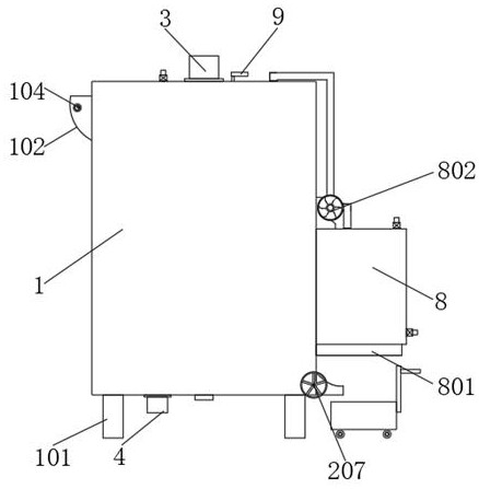
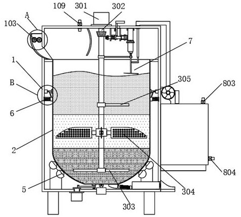
[0037] See Figure 1 - Figure 8 The present invention provides a technical solution: based sludge handling oilfield sludge separation device, comprising a housing 1, a feed hopper 102, a base 101, inlet valve 109, heater 801, oil 802, a single steam the valve 803, the oil solenoid valve 804, valve 207 and an evaporator mud tank 8, fixed to the base 101 is provided at the four corners of the bottom end of the housing 1, the evaporation tank 8 is fixed ...


PUM


Abstract

The invention relates to the technical field of oil-sludge separation equipment, and in particular, relates to oil-sludge separation equipment for an oil field based on oil-sludge treatment and a separation method of the oil-sludge separation equipment. The oil-sludge separation equipment comprises a shell, a separation tank, a feeding grinding assembly, an oil-sludge separation structure, a vibration separation structure, a deflection protection universal ball, a vibration stabilizing structure, a telescopic oil nozzle assembly, an evaporation box and a transmission switch assembly. Deep separation of the sludge is realized through grinding of large particles of the oil sludge, high-speed stirring and mixing, low-speed stirring and separation, oscillation separation and collection and recovery, so that the oil sludge is layered and separated more thoroughly, the equipment operation is simpler, the oil sludge separation is more efficient, and the problem that traditional equipment can only remove sludge on a surface layer by means of calcination evaporation and is low in efficiency is solved.

Description

Technical field [0001] Technical Field The present invention relates to a sludge separation device, particularly to an oil-based sludge-treated sludge with a separation device and a separation method. Background technique [0002] In oil exploration or oil leakage process, prone to oil sludge, oil sludge is a kind of oily solid waste, my country's petrochemical industry, will produce large amounts of oil sludge per year, causing great impacts on the environment; [0003] Existing devices typically use the high temperature calcination was evaporated, and the oil together with the evaporated water from the sludge, and oil and water collection process, but in the actual production process completely infiltrated Since the oil sludge, causing sludge mixed the more closely when the high temperature evaporation, only the surface of the evaporation of its oil, not to the depths of the oil sludge evaporation, it can not be deep separation; [0004] A solution is now proposed for the above...

Claims


Application Information

Patent Timeline
Patent Type & Authority Applications(China)
IPC IPC(8): C02F11/121B01F13/10
CPCC02F11/121C02F2303/26B01F33/831
Inventor 钟辉娟
Owner 东营金昱技术开发有限公司
Why Eureka
Try Eureka