Oilfield sludge separation equipment and separation method based on sludge treatment

An oil sludge separation and oil sludge technology, which is applied in the fields of sludge treatment, water/sludge/sewage treatment, special treatment targets, etc., can solve the problems of only removing the sludge on the surface, low efficiency, etc. Simple operation, efficient separation effect

Active Publication Date: 2021-10-26
东营金昱技术开发有限公司
View PDF6 Cites 0 Cited by
  • Summary
  • Abstract
  • Description
  • Claims
  • Application Information

AI Technical Summary

Problems solved by technology

[0005] The purpose of the present invention is to provide a kind of sludge separation equipment for oil field based on sludge treatment and its separation method: by setting the shell, separation tank, feed grinding assembly, sludge separation structure, vibration separation structure, deflection protection universal ball, telescopic Grease nozzle assembly, evaporator box and transmission switch assembly, grinding large particles of sludge, high-speed stirring and mixing, low-speed stirring and separation, vibration separation and collection and recovery, realize deep separation of sludge, make sludge stratification and separation more thorough, equipment The operation is simpler, and the separation of sludge is more efficient, which solves the problem that traditional equipment can only remove the sludge on the surface by calcination and evaporation, and the problem of low efficiency

Method used


Image

  • Oilfield sludge separation equipment and separation method based on sludge treatment
  • Oilfield sludge separation equipment and separation method based on sludge treatment
  • Oilfield sludge separation equipment and separation method based on sludge treatment

Examples


Embodiment Construction

[0036] The following will clearly and completely describe the technical solutions in the embodiments of the present invention with reference to the accompanying drawings in the embodiments of the present invention. Obviously, the described embodiments are only some, not all, embodiments of the present invention. Based on the embodiments of the present invention, all other embodiments obtained by persons of ordinary skill in the art without creative efforts fall within the protection scope of the present invention.

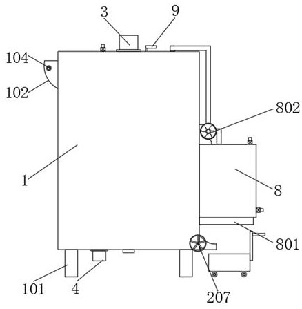
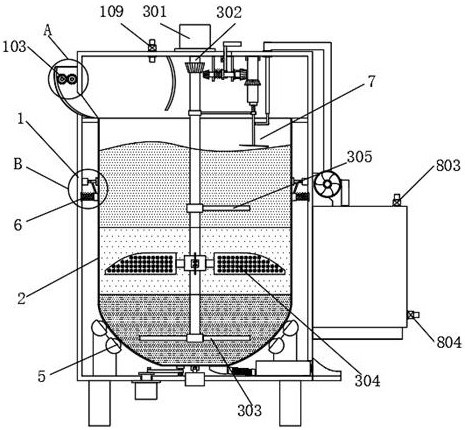
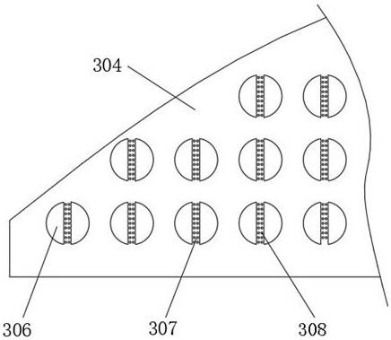
[0037] see Figure 1-Figure 8 , the present invention provides a technical solution: an oil sludge separation equipment for oil field based on sludge treatment, including a housing 1, a feed hopper 102, a base 101, a water inlet solenoid valve 109, a heater 801, an oil suction unit 802, a steam unit Directional valve 803, oil outlet solenoid valve 804, mud outlet valve 207 and evaporation box 8, base 101 are fixed at the four corners of the bottom end of casing 1, ...


PUM


Abstract

The present invention relates to the technical field of oil sludge separation equipment, in particular to oil sludge separation equipment for oil fields based on oil sludge treatment and a separation method thereof, including a shell, a separation tank, a feed grinding assembly, an oil sludge separation structure, an oscillation separation structure, and a deflection protection Universal ball, vibration and stable structure, telescopic oil nozzle assembly, evaporation box and transmission switch assembly; the present invention realizes the deep layer of sludge through grinding large particles of sludge, high-speed stirring and mixing, low-speed stirring and separation, vibration separation and collection and recovery. Separation makes the sludge layered and separated more thoroughly, the operation of the equipment is simpler, and the separation of the sludge is more efficient, which solves the problem that the traditional equipment can only remove the sludge on the surface by calcination and evaporation, and the efficiency is low.

Description

technical field [0001] The invention relates to the technical field of oil sludge separation equipment, in particular to oil sludge separation equipment for oil fields based on oil sludge treatment and a separation method thereof. Background technique [0002] In the process of oil exploitation or oil leakage, oily sludge is easy to be produced. Oily sludge is a kind of oily solid waste. In my country's petrochemical industry, a large amount of oily sludge is produced every year, which has a great impact on the environment; [0003] Existing equipment usually uses high-temperature calcination and evaporation to evaporate oil and water from the sludge together, and then collect and treat the oil and water. However, in the actual production process, the oil and sludge are mixed due to the complete infiltration of the oil into the sludge. When the high temperature evaporates, only the oil on the surface can be evaporated, and the oil in the deep part of the sludge cannot be eva...

Claims


Application Information

Patent Timeline
Patent Type & Authority Patents(China)
IPC IPC(8): C02F11/121B01F13/10
CPCC02F11/121C02F2303/26B01F33/831
Inventor 钟辉娟
Owner 东营金昱技术开发有限公司
Why Eureka
Try Eureka