Fabricated square steel bar net rack laminated slab

A technology of reinforced mesh frame and laminated board, which is applied to floors, buildings, building reinforcements, etc., can solve the problems of low strength and rigidity of the bottom plate of the laminated board, affecting the construction efficiency of the laminated board, and few construction steps, so as to avoid mechanical jamming. , to ensure the smoothness and reduce the effect of friction

Inactive Publication Date: 2021-08-31
CHONGQING UNIV
View PDF8 Cites 1 Cited by
  • Summary
  • Abstract
  • Description
  • Claims
  • Application Information

AI Technical Summary

Problems solved by technology

[0004] In view of this, the present invention solves the problems of low assembly efficiency, high difficulty in assembly, low strength and rigidity of the bottom plate of the laminated slab, mid-span support is required, and many construction steps affect the construction efficiency of the laminated slab in the existing assembly method of laminated slabs. A prefabricated square reinforced grid laminated slab is developed, which has the advantages of convenient and efficient on-site assembly of the laminated slab, no need for mid-span support, fewer construction steps, and high construction efficiency

Method used


Image

  • Fabricated square steel bar net rack laminated slab
  • Fabricated square steel bar net rack laminated slab
  • Fabricated square steel bar net rack laminated slab

Examples


Embodiment 1

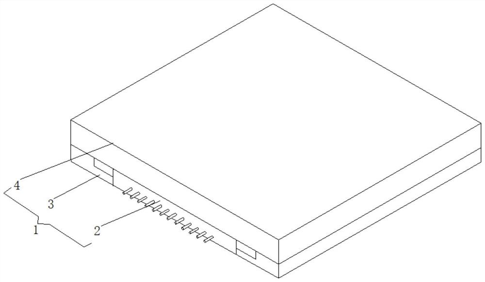
[0043] Such as Figure 1-Figure 3 Shown is a prefabricated square reinforced grid laminated plate, including a cuboid laminated plate 1, the laminated plate 1 includes a prefabricated bottom plate 2, two spliced ​​plates 3 and a post-casting layer 4, and the two spliced ​​plates 3 are arranged on the prefabricated bottom plate 2 The left and right sides of the two splicing plates 3 have the same connection structure and are arranged in the form of a mirror image. The post-casting layer 4 is formed by pouring concrete on the prefabricated bottom plate 2 and the two splicing plates 3 .

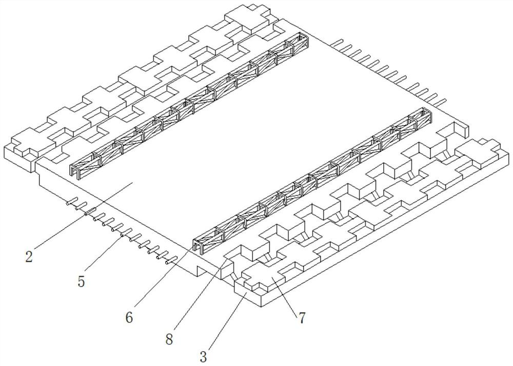
[0044] The prefabricated floor 2 is provided with a number of horizontal steel bars 5 extending out from the front and rear sides of the surface. The horizontal steel bars 5 are set according to the actual length of the prefabricated floor 2 without limitation in quantity. At the same time, the upper surface of the prefabricated floor 2 is provided with two The square truss bars 6 connected by t...

Embodiment 2

[0047] Such as Figure 1-Figure 7 The difference between Embodiment 2 and Embodiment 1 is that a prefabricated floor 2 is provided with several connection grooves 10 on the side surface of the splicing plate 3 facing the prefabricated bottom plate 2. The number of connection grooves 10 is based on The actual length of the splicing plate 3 is not limited in quantity. At the same time, there is a movable groove 17 in the precast concrete layer I7 which communicates with the connecting groove 10. Plate 11, one end of the connecting plate 11 facing away from the prefabricated bottom plate 2 extends into the connecting groove 10 and is slidably connected with the connecting groove 10. The movable groove 17 is slidably connected with a built-in connecting rod 13 whose lower end extends into the connecting groove 10. The built-in connecting rod 13 is located at one end in the connection groove 10 and is fixedly sleeved with a limit ring 14. The upper surface of the limit ring 14 is f...


PUM


Abstract

The invention relates to a fabricated square steel bar net rack laminated slab. The laminated slab comprises a prefabricated bottom plate, two splice plates and a post-pouring layer, a plurality of horizontal steel bars extending out of the surfaces of the front side and the rear side of the prefabricated bottom plate are arranged on the prefabricated bottom plate, square truss steel bars are fixedly connected to the upper surface of the prefabricated bottom plate, fabricated concrete layers I are poured on the two splice plates correspondingly, fabricated concrete layers II matched with the fabricated concrete layers I are poured on the surfaces of the left side and the right side of the fabricated bottom plate correspondingly, and the thickness of the fabricated bottom plate is equal to the sum of the splice plates and the thickness of the fabricated concrete layers I. According to the fabricated square steel bar net rack laminated slab, the laminated slab is more convenient to assemble, the operation difficulty of assembling the laminated slab is reduced, and the speed and efficiency of assembling the laminated slab are improved.

Description

technical field [0001] The invention belongs to the field of prefabricated concrete buildings, in particular to a prefabricated square reinforced grid laminated plate. Background technique [0002] The laminated slab is an assembled integral floor slab formed by laminating prefabricated slabs and cast-in-place reinforced concrete layers. The laminated floor slab has good integrity, and the upper and lower surfaces of the slab are flat, which is convenient for decoration of the facing layer. It is generally applicable to high-rise buildings and large-bay buildings that require high overall rigidity. [0003] Laminated slabs have been widely used in the building construction process. Because of their convenient installation, the construction period has been greatly shortened. There are many types of laminated slabs in the technology used in the market. The splicing technology between laminated slabs is usually in the form of Keyway type, traditional type, overall lap joint ty...

Claims


Application Information

Patent Timeline
Patent Type & Authority Applications(China)
IPC IPC(8): E04B5/17E04C5/01E04C5/06
CPCE04B5/17E04C5/01E04C5/06
Inventor 白久林邓子豪陈辉明杨经纬金双双胡少伟
Owner CHONGQING UNIV
Why Eureka
Try Eureka