Vehicle-mounted MIMO radar random coding waveform modulation method

A technology of random coding and modulation method, which is applied in the direction of radio wave measurement systems, instruments, etc., can solve the problems of increasing radar antenna aperture, poor anti-interference ability, and long detection distance, so as to improve anti-interference ability and increase robustness Effect

Active Publication Date: 2021-08-31
谭文举
View PDF8 Cites 1 Cited by
  • Summary
  • Abstract
  • Description
  • Claims
  • Application Information

AI Technical Summary

Problems solved by technology

[0003] The existing vehicle-mounted millimeter-wave radars are mainly designed and developed for highway scenarios. For rail transit scenarios, there are problems such as short detection distance, low azimuth resolution, and poor anti-interference ability, which are difficult to meet the application needs. MIMO (multiple transmission and multiple reception) millimeter-wave radars Through the cascading technology of multi-radio frequency chips, the antenna aperture of the radar is effectively increased, which has the characteristics of high resolution and long detection distance, and can increase the diversity of target information and improve the anti-jamming ability of the radar.
The current MIMO radars mostly use time-sharing MIMO waveforms. Under the high-speed moving platform of the train, there are shortcomings such as short detection distance, low angle measurement accuracy, and poor anti-interference ability.
In the rail transit industry, the on-board millimeter-wave radar for trains needs to achieve high-precision detection of long-distance obstacles. At the same time, due to the large amount of noise interference in the rail transit scene, the millimeter-wave radar using the traditional time-sharing MIMO waveform may not meet the actual requirements. need

Method used


Image

  • Vehicle-mounted MIMO radar random coding waveform modulation method
  • Vehicle-mounted MIMO radar random coding waveform modulation method

Examples


Embodiment Construction

[0021] In order to make the object, technical solution and advantages of the present invention clearer, the present invention will be described in further detail below with reference to the accompanying drawings and preferred embodiments. However, it should be noted that many of the details listed in the specification are only for readers to have a thorough understanding of one or more aspects of the present invention, and these aspects of the present invention can be implemented even without these specific details.

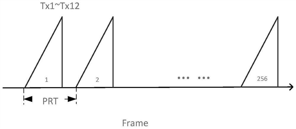
[0022] According to a kind of vehicle-mounted MIMO radar random coding waveform modulation method of the present invention, at first, the transmitting mode and the receiving mode of radar are set to random coding mode; And random signal generator is set in the processor of radar, when transmitting radar signal , reset the random signal generator in the processor according to a certain time interval, the transmission pulse repetition period is: 41.667us, under this...


PUM


Abstract

The invention discloses a vehicle-mounted MIMO radar random coding waveform modulation method, and belongs to the field of millimeter wave radars. The method includes the following steps: setting a radar to be in a random coding mode; by arranging a random signal generator, when a radar signal is transmitted, resetting the random signal generator, and generating a group of random codes; after a random code is generated, writing the random code into a register, wherein when the radar transmits a radar signal every time, the radar signal is modulated by calling the code in the register; and inputting the demodulated data in the radio frequency chip into a decoder to generate a decoded receiving signal, so that a receiving end can receive an echo signal reflected after the emitted radar signal encounters an obstacle. According to the invention, each transmitted pulse initial phase is randomly coded in the processor, and transmitted signals of different codes do not interfere with each other, so that a plurality of millimeter wave radars can be used in the same environment, the robustness of the system is improved, and the anti-interference capability of the rail transit radar can be greatly improved.

Description

technical field [0001] The invention relates to the technical field of millimeter-wave radar, in particular to a random coding waveform modulation method for vehicle-level MIMO radar. Background technique [0002] With the rapid development of millimeter-wave chip technology, millimeter-wave radar has been widely used in civilian markets such as autonomous driving, smart security, smart transportation, and smart home. Compared with sensors such as lasers, ultrasonic waves, and cameras, millimeter-wave radar has the advantages of long detection distance, all-weather, and high reliability. [0003] The existing vehicle-mounted millimeter-wave radars are mainly designed and developed for highway scenarios. For rail transit scenarios, there are problems such as short detection distance, low azimuth resolution, and poor anti-interference ability, which are difficult to meet the application needs. MIMO (multiple transmission and multiple reception) millimeter-wave radars Through ...

Claims


Application Information

Patent Timeline
Patent Type & Authority Applications(China)
IPC IPC(8): G01S7/28G01S7/282G01S7/02
CPCG01S7/28G01S7/282G01S7/023Y02D30/70
Inventor 谭文举任崇会潘文波
Owner 谭文举
Why Eureka
Try Eureka