Zero adjustment method for rotary transformer of permanent magnet motor

A resolver and zero position adjustment technology, which is applied to the control of generators, motor generators, electromechanical brakes, etc., can solve problems such as motor phase sequence and resolver wiring detection

Active Publication Date: 2021-08-31
江苏交科能源科技发展有限公司 +1
View PDF12 Cites 1 Cited by
  • Summary
  • Abstract
  • Description
  • Claims
  • Application Information

AI Technical Summary

Problems solved by technology

The prior art achieves resolver zero adjustment under low voltage, but high voltage resolver zero adjustment has not been reported; in the process of resolver zero adjustment, the motor phase sequence and resolver wiring are not detected, and there are problems of accuracy, versatility and safety

Method used


Image

  • Zero adjustment method for rotary transformer of permanent magnet motor
  • Zero adjustment method for rotary transformer of permanent magnet motor
  • Zero adjustment method for rotary transformer of permanent magnet motor

Examples


Embodiment Construction

[0029] The following will clearly and completely describe the technical solutions in the embodiments of the present invention with reference to the accompanying drawings in the embodiments of the present invention. Obviously, the described embodiments are only some, not all, embodiments of the present invention.

[0030] Unless otherwise defined, all technical and scientific terms used herein have the same meaning as commonly understood by one of ordinary skill in the technical field of the invention. The terms used herein in the description of the present invention are for the purpose of describing specific embodiments only, and are not intended to limit the present invention. As used herein, the term "and / or" includes any and all combinations of one or more of the associated listed items.

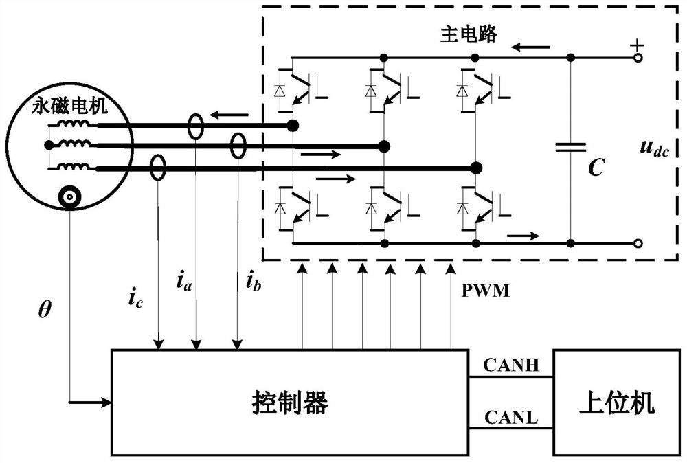
[0031] The resolver includes a resolver rotor and a resolver stator. The resolver rotor is sleeved on the motor rotor. The resolver rotor is fixed on the motor rotor and is coaxial with t...


PUM


Abstract

The invention provides a zero adjustment method for a rotary transformer of a permanent magnet motor. The method comprises the steps that an upper computer sends a rotary transformer zero adjustment instruction to a motor controller through a CAN bus; the motor controller increases the d-axis instruction voltage ud by taking 0.0001 as a step, the q-axis instruction voltage uq is zero, and the rotor position angle instruction is 0 degree; the A-phase winding current of the motor is compared with the rotary transformer zeroing current instruction until the A-phase winding current Ia is equal to the rotary transformer zeroing current instruction, and the d-axis instruction voltage at the moment is a fixed value ud0; a rotary transformer digital quantity is read, and a rotary transformer stator is manually adjusted; the upper computer sends a motor positioning angle of 120 degrees; the rotation digital quantity of the rotor with the position angle of 120 degrees is read; a rotor position angle instruction is 240 degrees; a rotation digital quantity Ang240 is read when the position angle of the rotor is 240 degrees; and zeroing is finished. According to the permanent magnet motor rotary transformer zero adjustment method provided by the invention, the problem of rotary transformer zero adjustment under high bus voltage can be solved; and the problems of phase sequence detection and rotary transformer wiring detection of the motor are synchronously solved in the rotary transformer zero setting process.

Description

technical field [0001] The present application relates to the technical field of motor control, in particular to a method for adjusting the zero position of a resolver for a permanent magnet motor. Background technique [0002] Due to the high efficiency and high power density of the permanent magnet motor, it has become the mainstream drive motor in the field of electric vehicles. The high-quality control of the permanent magnet motor requires accurate detection of the rotor electrical angle. Resolver, referred to as resolver, is an electromagnetic sensor, also known as a synchronous resolver. It is a small AC motor for measuring angles, used to measure the angular displacement and angular velocity of the rotating object, and consists of a stator and a rotor. [0003] The reason why the permanent magnet servo motor uses an angle sensor such as a resolver is to perform vector control, so that the electromagnetic field generated by the stator winding is always orthogonal to ...

Claims


Application Information

Patent Timeline
Patent Type & Authority Applications(China)
IPC IPC(8): H02P21/22H02P27/08
CPCH02P21/22H02P27/08
Inventor 黄健王健徐详冬王晨周洋韩建斌陈玮王勤王梓屺郭乐之
Owner 江苏交科能源科技发展有限公司
Why Eureka
Try Eureka