After-edge phase controlled light modulator
A phase controller and phase control technology, applied in the field of light source electronics, can solve the problems of stability and reliability, dimming, etc., and achieve the effects of improving work efficiency, low cost, and reducing fatigue
Inactive Publication Date: 2003-12-31
FUDAN UNIV
View PDF0 Cites 0 Cited by
- Summary
- Abstract
- Description
- Claims
- Application Information
AI Technical Summary
Problems solved by technology
[0002] At present, the commonly used silicon controlled rectifier (SCR) dimmer belongs to the dimmer of cutting-edge phase control, and generally can only be used for dimming incandescent lamps, and cannot be used for electronic energy-saving lamps, electronic ballast fluorescent lamps and fluorescent lamps that present capacitive impedance. Electronic transformer low-voltage halogen tungsten lamps (electronic spotlights), etc. for stable and reliable dimming
Method used
View moreImage
Smart ImageViewing Examples

Examples
Embodiment Construction
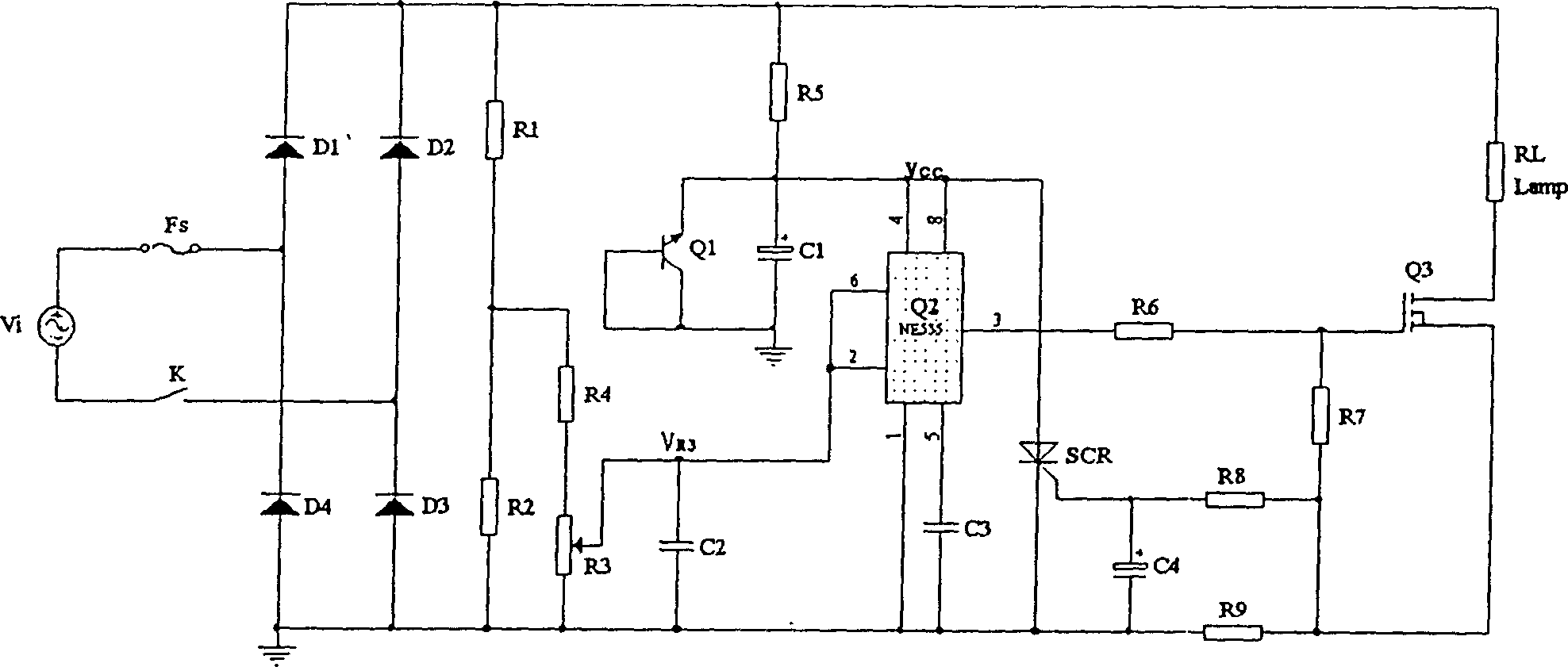
[0027] 220V MOS-1 dimmer as an example, its electrical schematic diagram is as follows figure 1 As shown, the values of the components are: Vi: 220V 50Hz C 1 : CD11 100μF / 16 Fs: 1A / 250V C 2 : CH111 47nF / 63D 1 ~D 4 : 1N4007C 3 : CH111 10nF / 63R 1 : RT14 0.25W 240KΩ C 4 : CD11 47μF / 16R 2 : RT14 0.25W 22KΩ Q 1 : S9013R 3 +R 2 : WXD3-13 22KΩ Q 2 : NE555R 5 : 2pcs 1W 100KΩ in parallel Q 3 : (1)IRF820(60W) (2)IRF830(100W)R 6 , R 8 : RT14 0.25W 5.1KΩ (3)IRF840(200W) (4)IGBT(1000W) R 7 : RT14 0.25W 360KΩ SCR: BT169 (V AK >50V) R 9 : RT14 0.25W 0.5~2Ω R L : dimmed bulb
[0028] (1)≤60W (2)≤100W
[0029] (3)≤200W (4)≤1000W
[0030] After installation in the usual way, a 220V MOS-1 dimmer can be obtained.
Login to View More PUM
 Abstract
The invention is related to a light modulator using after-edge phase controllation consists of a light modulating controllor, an electronic after-edge phase controllor, an active switch, an overload protective circuit and a sealed out casing. The after-edge phase controlled light modulator using MOSFET or IGBT as active switch is also called MOS or IGBT light modulator. MOS-1, MOS-2 and MOS-3 modes are suited to be used for electric network in 220-277 V and 100-277 V. Said light modulator can do modulating for not only filament lamp but also electric energy-conserving lamp, electric ballast fluorescent lamp and electric radio lamp with capacitive impedance, it is a new and high technology product to replace silicon controlled light modulator.
Description
technical field [0001] The invention belongs to the field of light source electronics and relates to a dimmer for lamps. Background technique [0002] At present, the commonly used silicon controlled rectifier (SCR) dimmer belongs to the dimmer of cutting-edge phase control, and generally can only be used for dimming incandescent lamps, and cannot be used for electronic energy-saving lamps, electronic ballast fluorescent lamps and fluorescent lamps that present capacitive impedance. Electronic transformer low-voltage halogen tungsten lamps (electronic spotlights), etc. can be dimmed stably and reliably. Contents of the invention [0003] The object of the present invention is to propose a dimmer which can not only dim incandescent lamps, but also stably and reliably dim electronic energy-saving lamps, fluorescent lamps with electronic ballasts and electronic spotlights with capacitive impedance. [0004] The dimmer proposed by the invention is composed of a dimmer control...
Claims
Login to View More Application Information
Patent Timeline
 IPC IPC(8): H05B37/02H05B41/392
Inventor 杨根元杨文斌
Owner FUDAN UNIV